
Weilin Cheng, Fang Zhang, Dongliang Lin, Aijun Zeng, Baoxi Yang, Huijie Huang. High Precision Correction Method of Illumination Field Uniformity for Photolithography Illumination System[J]. Acta Optica Sinica, 2018, 38(7): 0722001
- Acta Optica Sinica
- Vol. 38, Issue 7, 0722001 (2018)
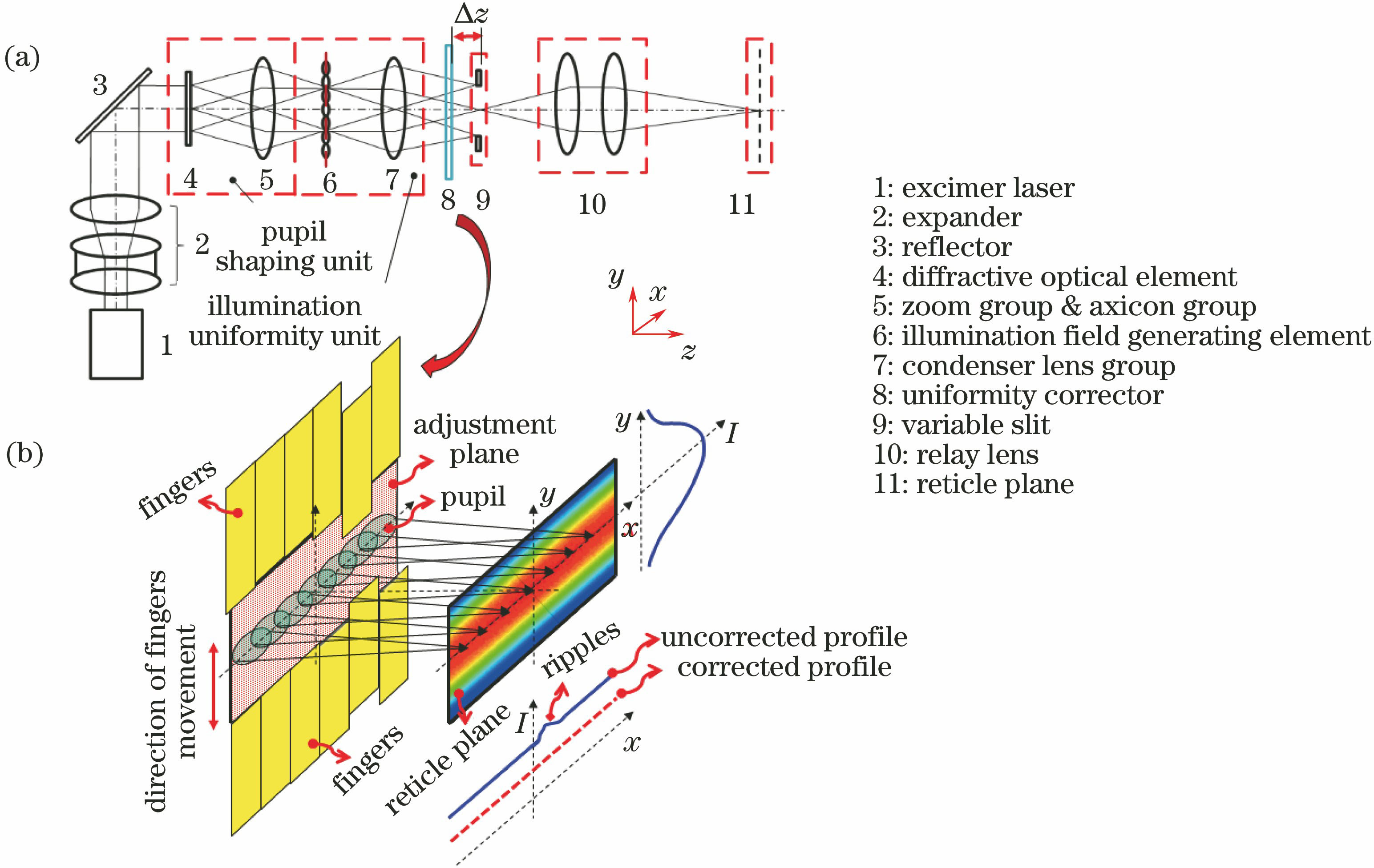
Fig. 1. Schematics of illumination system including finger array uniformity corrector. (a) Schematic of photolithography illumination system; (b) schematic of integral uniformity corrector for illumination system
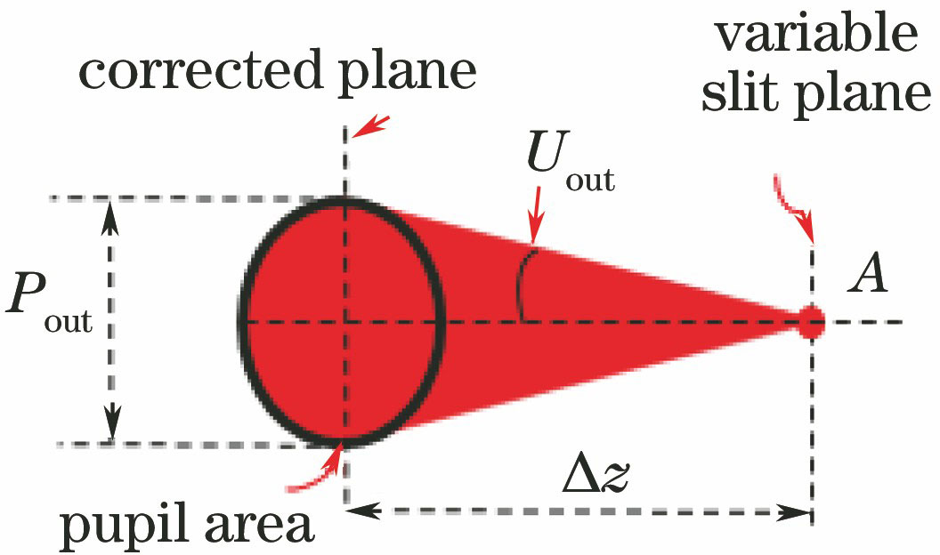
Fig. 2. Schematic of illumination field point at the focal plane of condenser lens group and its corresponding spread area at the adjustment plane (e.g. conventional illumination mode)
Fig. 3. Schematic of relationship between fingers and pupil shape area in the correction plane
Fig. 4. Schematic of shape and layout of fingers in general finger array correction method
Fig. 5. Schematics of adjustment process for general finger array correction methods. (a) Uncorrected illumination filed; (b) corrected by one pair of fingers; (c) corrected by two pairs of fingers
Fig. 6. Schematics of adjustment process for uniformity correction method with staggered fingers. (a) Uncorrected illumination filed; (b)-(g) single corrected process
Fig. 7. Schematics of structure of finger fore-end
Fig. 8. Schematics of correction effect of different structures of finger fore-end. (a) Chamfer rectangle; (b) circle rectangle
Fig. 9. Schematic of adjustment for uniformity correction method with staggered and chamfered fingers
Fig. 10. Schematic of adjustment for uniformity correction method with staggered, chamfered and double layout fingers
Fig. 11. Simulation model of 65 nm node lithography illumination system
Fig. 12. Layoutstructure of staggered fingers
Fig. 13. Layout structure of staggered and chamfered fingers
Fig. 14. Integral uniformity distributions adjusted by different fingers arrangements. (a) Conventional illumination mode with σ=0.15; (b) conventional illumination mode with σ=0.93; (c) annular illumination mode with σin=0.16 and σout=0.36; (d) annular illumination mode with σin=0.76 and σout=0.96
Fig. 15. Layoutstructure of staggered, chamfered and double layout fingers
Fig. 16. Integral uniformity distributions adjusted by staggered, chamfered and double layout fingers arrangement. (a) Conventional illumination mode with σ=0.15; (b) conventional illumination mode with σ=0.93; (c) annular illumination mode with σin=0.16 and σout=0.36; (d) annular illumination mode with σin=0.76 and σout=0.96
| ||||||||||||||||||||||
Table 1. Summary of results of corrected illumination integrated uniformity

Set citation alerts for the article
Please enter your email address
© Copyright 2018-2021 | Chinese Laser Press. All Rights Reserved 沪ICP备15018463号-20