
Yuanyuan Wang, Yi He, Ling Wei, Xiqi Li, Jinsheng Yang, Hong Zhou, Yudong Zhang. Bimorph deformable mirror based adaptive optics scanning laser ophthalmoscope for retina imaging in vivo [J]. Chinese Optics Letters, 2017, 15(12): 121102
- Chinese Optics Letters
- Vol. 15, Issue 12, 121102 (2017)
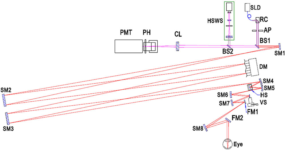
Fig. 1. Schematic of AOSLO system. SM1–SM8: spherical mirrors, FM: flat mirror, CL: collecting lens, PH: confocal pinhole, HS: horizontal scanner, VS: vertical scanner, RC: reflecting collimator. AP: aperture.
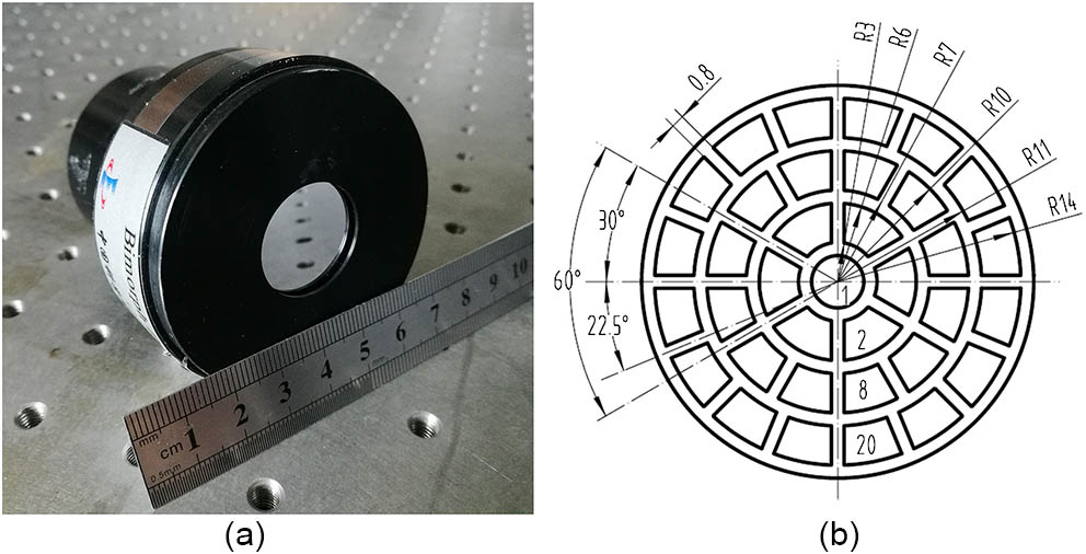
Fig. 2. (a) 35-actuator bimorph DM, (b) distribution of 1–35 discrete electrodes. The radius of electrode 1 is 2 mm; the outer radius is 6, 10, and 14 mm for the second, third and fourth ring, respectively. There are 0.8 and 1 mm wide gaps for the angle and radial direction, respectively.
Fig. 3. Initial flatness of the DM (a) without correction and (b) with self-correction.
Fig. 4. Peak valley values as the measured influence function of the applied voltages. The solid points correspond to the obtained mirror deformation, while the dashed lines are the corresponding fits performed over each set of data.
Fig. 5. Color-coded aberration maps. Top row: initial aberrations from 4 real eyes. Bottom row: best corrected wavefront aberrations estimated by the HSWS.
Fig. 6. (Color online) Zernike coefficients of the human eye without AO correction in the green color, and with AO correction in the red color.
Fig. 7. (Color online) Single frame (a) without AO correction, (b) without AO correction but after the best correction of the defocus and astigmatism aberrations, (c) with AO correction. The images are 512 × 449

Set citation alerts for the article
Please enter your email address
© Copyright 2018-2021 | Chinese Laser Press. All Rights Reserved 沪ICP备15018463号-20