A bimorph deformable mirror (DM) with a large stroke of more than 30 μm using 35 actuators is presented and characterized for an adaptive optics (AO) confocal scanning laser ophthalmoscope application. Facilitated with a Shack–Hartmann wavefront sensor, the bimorph DM-based AO operates closed-loop AO corrections for human eyes and reduces wavefront aberrations in most eyes to below 0.1 μm rms. Results from living eyes, including one exhibiting of myopia and of astigmatism along with notable high-order aberrations, reveal a practical efficient aberration correction and demonstrate a great benefit for retina imaging, including improving resolution, increasing brightness, and enhancing the contrast of images.
In an adaptive optics scanning laser ophthalmoscope (AOSLO), the ocular aberrations of the test subjects are measured by a wavefront sensor [such as the Harmann–Shack wavefront sensor (HSWS)], and subsequently minimized by a wavefront corrector [usually called a deformable mirror (DM)][1–4]. Therefore, a key device in AOSLO systems is the DM, essentially consisting of a mirrored surface whose shape can be controlled by means of actuators. Many DMs, such as a microelectromechanical systems (MEMS)-based DM[5,6], a piezoelectric-based DM[7,8], an electromagnetic DM[9–11], a liquid-crystal spatial light modulator[12], etc., have been investigated to compensate for the ophthalmic aberrations in many AOSLO systems.
However, population studies have shown that human eyes have large amounts of low-order aberrations (defocus and astigmatism)[13,14], and therefore a high dynamic range for wavefront correction is needed. Most kinds of DMs have a limited dynamic range (around 4 μm of DM stroke or 8 μm of aberration correction). Thus, a careful selection of trial lenses should be added for pre-correcting subjects’ low-order aberrations[15,16]. Some electromagnetic DMs have larger strokes but often are limited in the correction of high-order aberrations, and still complex and a high costto fabricate[17,18].
For these reasons, we adopted a bimorph DM to build a robust adaptive optics (AO) for our AOSLO. Compared to other DMs, the bimorph DM has a larger stroke, a higher damage threshold of laser power, a lower cost, and a simple fabrication and application[19–21]. Preponderantly, ocular aberrations mainly focus in low orders, and the bimorph DM has a better correction of low-order aberrations with a given number of actuators due to a maximum stroke of dozens of microns.
Sign up for Chinese Optics Letters TOC. Get the latest issue of Chinese Optics Letters delivered right to you!Sign up now
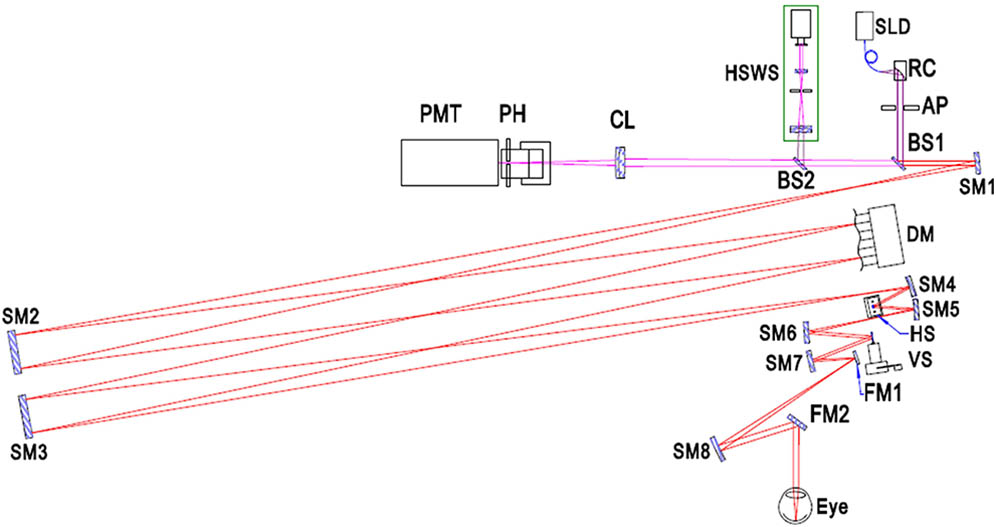
Shown in Fig. 1 is the bimorph DM-based AOSLO. The AOSLO system is a double pass system including a superluminescent laser diode (SLD), horizontal and vertical scanners, a wavefront sensor, a bimorph DM, and a photomultiplier tube (PMT) detector. Spherical mirrors in an off-axis arrangement are used to relay the planes conjugate to the pupil of the eye to avoid undesired back-reflections. These mirrors are used in pairs creating an afocal telescope to preserve conjugate planes and match optics apertures.
A low-coherence SLD (SLD-381-HP, Superlum, Ireland) is collimated by an reflective collimator (RC08FC-P01, Thorlabs, USA) to illuminate the subject’s retina. A beam splitter (BS2) directs a small portion of the imaging light to the HSWS while the remainder passes through to the PMT detector (H7422-20, Hamamatsu, Japan) for imaging. The HSWS uses a square lenslet array of pitch and 5 mm focal length. A digital CCD camera (manta G046B ASG, AVT, Germany) detects the focused spots and provides aberration measurement at about 30 Hz, and aberrations are fit to a 7th-order Zernike polynomial[22].
In order to achieve a greater deformation stroke, a thinner optically polished glass and two piezoelectric ceramic (PZT) layers structure are adopted to manufacture the bimorph DM. However, the glass should have enough strength to support the DM body. Compromising the structure strength and deformation requirement, the glass thickness is 1.0 mm and the piezoelectric layer thickness is 0.4 mm. Figure 2(a) presents a photograph of the bimorph DM, and the distribution of the actuators underneath the deformable membrane is shown in Fig. 2(b). The discrete electrodes are arranged in a fan supporting mount shape. All electrodes exerted by the same voltage will produce a defocus phase, and different voltages on the fan-shaped electrodes can produce an astigmatism phase. Thus, even numbers of fan-shaped electrodes take into account the astigmatism of the 0° and 45° directions, and is able to correct astigmatism in any direction.
Figure 2.(a) 35-actuator bimorph DM, (b) distribution of 1–35 discrete electrodes. The radius of electrode 1 is 2 mm; the outer radius is 6, 10, and 14 mm for the second, third and fourth ring, respectively. There are 0.8 and 1 mm wide gaps for the angle and radial direction, respectively.
The bimorph DM surface covers an active aperture of 20 mm, and is coated with a silver high-reflection film in both the visible and near-infrared domains. According to the manufacturer, the initial flatness of the DM is 1.803 μm peak–valley value (PV), and 0.475 μm rms over the entire pupil as measured by the Zygo interferometer (Zygo MARK IV, measurement accuracy @ PV and @ rms ) and is shown in Fig. 3(a). Compared to conventional stack actuator DMs, The initial surface flatness is slightly worse, and the main reason is that the bimorph mirror is too thin to fabricate, and a thinner mirror can produce a much larger deformation. Thus, the initial surface aberrations that can be self-corrected benefited from the large stroke. With self-correction, the surface flatness is 0.048 μm PV and 0.008 μm rms over the whole area, and is presented in Fig. 3(b). Voltages loaded for self-correction are no more than , and only occupy 5.7% of the maximum permission voltage (). Therefore, the initial surface aberrations can be compensated by self-correction, and will not have any impact on the correction ability.
Figure 3.Initial flatness of the DM (a) without correction and (b) with self-correction.
The influence function is one key parameter to characterize the capability of DMs in correcting aberrations, which is the response of the membrane to a given voltage applied to every actuator. According to the fabrication, the range of voltage in this bimorph DM is . However, the voltages must be limited to prevent the DM to be loaded to larger voltages, which would permanently damage the DM. In this study, the influence function of the bimorph DM was calibrated as follows: first, zero voltages were applied to all actuators to produce a reference wavefront. Second, a series of voltages from to 200 V with an increment of 20 V were loaded to all actuators to push (or pull) the DM mirror. At each increment, the change wavefront was measured by the Shack–Hartmann sensor, and the PV of the wavefront difference map between the changed wavefront and the reference wavefront is the mirror deformation. Therefore, the influence function can be calibrated in sequence, and has been present in Fig. 4.
Figure 4.Peak valley values as the measured influence function of the applied voltages. The solid points correspond to the obtained mirror deformation, while the dashed lines are the corresponding fits performed over each set of data.
There is apparent linearity when positive voltages are loaded to push the mirror in Fig. 4(a), and the obtained linear equation is where is the square of the linear correlation coefficient, with a value of 0.99 indicating a near-perfect linear fit.
However, there is nonlinearity when negative voltages are loaded to pull the mirror, as can be seen in Fig. 4(b). The nonlinearity of the influence function can be fitted as:
This phenomenon can be explained by the limitation of the piezoelectric material. The hysteresis and creep phenomena are inherent properties of this material, and the actuator response can be approximated to a linear curve over the full voltage range. The nonlinearity was ignored in the present study, since the influence function was evaluated from the difference of two measurements of the same actuator, and normalized by the full voltage range. This double measurement is effective to cancel out the nonlinearity effect of the DM mirror over half the voltage range.
Prior to the human subject imaging by the bimorph DM-based AOSLO system, the human eyes were artificially dilated (one topically applied drop each of 0.5% tropicamide and 2.5% phenylephrine), and the pupil size is limited to 6.0 mm diameter. The illumination power for the 795 nm SLD is always kept below 200 μW, times below the ASNI safe exposure level. Subjects are fixed to the system by using a bite bar, with their dental impression, mounted on a three-dimensional stage allowing for accurate centering.
Incorporated with a custom-made HSWS for measuring the ocular aberrations, the aberration correction of this AOSLO system is shown in Fig. 5, where initial aberrations (top row) and the corrected aberrations (bottom row) achieved for each subject are presented.
Figure 5.Color-coded aberration maps. Top row: initial aberrations from 4 real eyes. Bottom row: best corrected wavefront aberrations estimated by the HSWS.
Note that hundreds of subjects have been corrected to better than 0.1 μm rms, and we randomly chose four subjects for further study here. In fact, initial aberrations consist of large amounts of low-order aberrations, particularly for the defocus, and there presented several myopias in Fig. 5. The rms with AO correction is notably low, ranging from 0.018 to 0.099 μm in all cases above the diffraction limit. A particular hyperopia S3 () is also depicted in Fig. 5, and a remaining aberration rms of 0.073 μm is achieved. A notable myopia ( defocus and astigmatism, measured with the HSWS) with some high-order aberrations is presented in subject S4. The initial aberration presents more than 13 μm PV. With AO correction of the bimorph DM, the remaining aberration rms is 0.099 μm. This particular case is further studied in Fig. 6. The bar diagram explicitly shows the values of the different aberrations without and with AO correction up to the 7th order, in green and red color, respectively. With an AO correction of 10 iterations (1/3 s), all aberration coefficients are decreased to small values, and the remaining aberrations are mainly high order.
Figure 6.(Color online) Zernike coefficients of the human eye without AO correction in the green color, and with AO correction in the red color.
In Fig. 7 we present images of the retina of subject S4 without and with AO corrections to characterize the system performance, and the power spectra of the images are also here, where the Fourier spectrum for each frequency is radially integrated. Without AO corrections, there is nothing to be distinguished in Fig. 7(a). With the bimorph DM correction of only the defocus and astigmatism aberrations, the power spectra of Fig. 7(b) are increased at low frequencies and decreased at high frequencies, respectively. It indicates that the image resolution corresponding to low frequencies is improved and the noises corresponding to high frequencies are suppressed. With AO correction of all aberrations, the spatial frequency around the Yellot’s ring[23] that is highlighted by an arrow is further increased, which determines the highest resolvable spatial frequency. The radius of the Yellot’s ring in Fig. 7(c) is about 97 cycles/degree. According to the Raleigh criteria, the minimum resolution for a 6.0 mm pupil at the wavelength of 795 nm is about 2.65 μm (105 cycles/degree in spatial frequency) for a modified Gullstrand eye model[24], and the retina image with AO correction is very close to the Raleigh diffraction limit.
Figure 7.(Color online) Single frame (a) without AO correction, (b) without AO correction but after the best correction of the defocus and astigmatism aberrations, (c) with AO correction. The images are pixels, and the field of view subtends 2°, or approximately 580 μm on one side. The image was taken from a retina location about 4.5° from the fovea center. The scale bar is 50 μm.
To measure the quality of the retina images, the contrast of image is defined as where , , and represents the mean of image . The contrasts of the images in Fig. 7 are (a) 4.3279, (b) 10.0771, (c) 24.2711, respectively. Large values of Con indicate that the image covers more gray scale, and the image contrast and quality are improved with AO correction.
In conclusion, we develop a bimorph DM-based AOSLO system that uses 35 actuators with an aperture of 20 mm to produce large strokes of more than 30 μm. The bimorph DM has a flat surface of 8 nm rms with self-correction, and an approximately linear response with applied voltage can be achieved through the double measurement of the influence functions. Facilitated with an SHWS, the bimorph-DM-based AO operates a closed-loop AO correction for the human eye and reduces wavefront aberrations in most eyes to below 0.1 μm rms. Results from living human eyes, including one exhibiting of myopia and of astigmatism along with some notable high-order aberrations, reveal a practical efficient aberration correction and demonstrate a great benefit for retina imaging, including improving resolution, increasing brightness, and enhancing contrast of images.