• Laser & Optoelectronics Progress
  • Vol. 55, Issue 4, 041405 (2018)
Jingang Xu1, Yong Chen1, Hui Chen、*, and Bing Yang1
Author Affiliations
  • 1 School of Materials Science and Engineering, Southwest Jiaotong University, Chengdu, Sichuan 610031, China
  • 1 State Key Laboratory of Traction Power, Southwest Jiaotong University, Chengdu, Sichuan 610031, China
  • show less
    DOI: 10.3788/LOP55.041405 Cite this Article Set citation alerts
    Jingang Xu, Yong Chen, Hui Chen, Bing Yang. Influence of Process Parameters on Forming Defects of H13 Steel Processed by Selective Laser Melting[J]. Laser & Optoelectronics Progress, 2018, 55(4): 041405 Copy Citation Text show less
    Single-channel morphologies under different laser powers. (a) 250 W; (b) 300 W; (c) 350 W; (d) 400 W; (e) 450 W
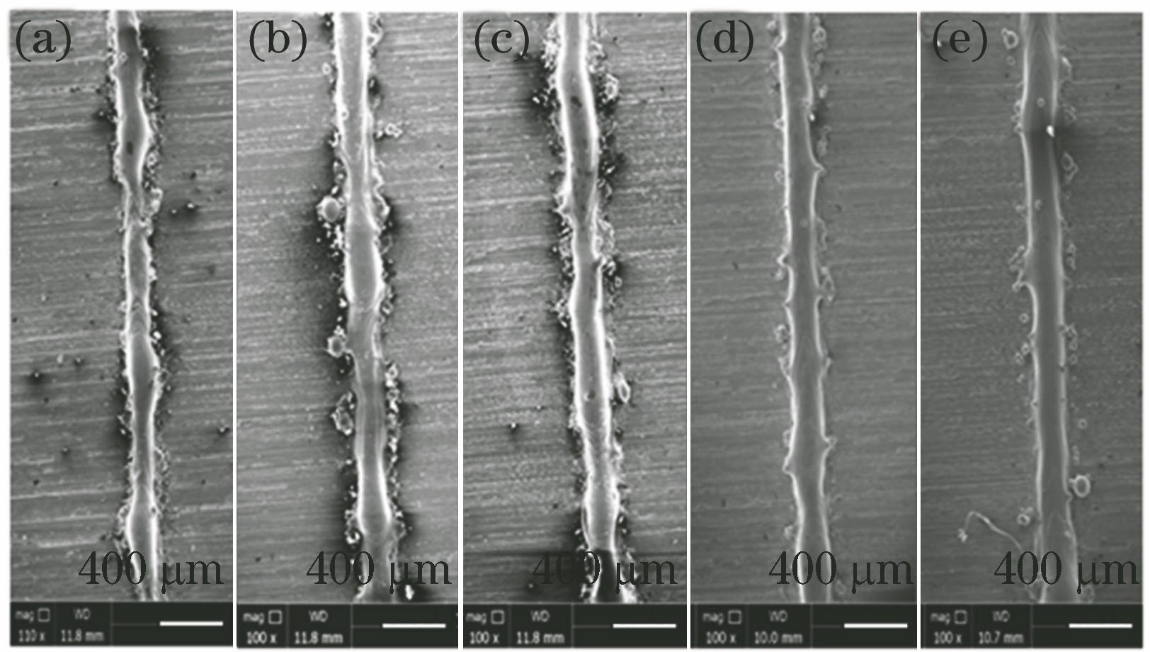
    Fig. 1. Single-channel morphologies under different laser powers. (a) 250 W; (b) 300 W; (c) 350 W; (d) 400 W; (e) 450 W
    Single-channel morphologies under different scanning speeds. (a) 800 mm?s-1; (b) 1000 mm?s-1; (c) 1200 mm?s-1; (d) 1400 mm?s-1; (e) 1600 mm?s-1
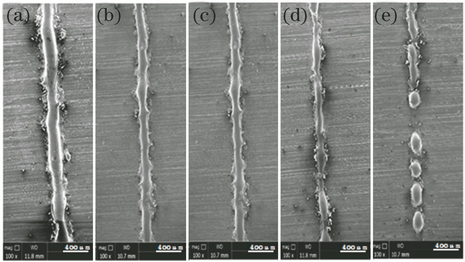
    Fig. 2. Single-channel morphologies under different scanning speeds. (a) 800 mm?s-1; (b) 1000 mm?s-1; (c) 1200 mm?s-1; (d) 1400 mm?s-1; (e) 1600 mm?s-1
    Effect of laser power on forming part quality.(a) 250 W; (b) 350 W; (c) 400 W; (d) 450 W
    Fig. 3. Effect of laser power on forming part quality.(a) 250 W; (b) 350 W; (c) 400 W; (d) 450 W
    Effect of scanning speed on forming part quality. (a) 300 mm?s-1; (b) 400 mm?s-1; (c) 500 mm?s-1; (d) 800 mm?s-1; (e) 1200 mm?s-1
    Fig. 4. Effect of scanning speed on forming part quality. (a) 300 mm?s-1; (b) 400 mm?s-1; (c) 500 mm?s-1; (d) 800 mm?s-1; (e) 1200 mm?s-1
    Effect of scanning spacing on forming part quality. (a) 40 μm; (b) 60 μm; (c) 70 μm; (d) 80 μm
    Fig. 5. Effect of scanning spacing on forming part quality. (a) 40 μm; (b) 60 μm; (c) 70 μm; (d) 80 μm
    Schematic of SLM scanning strategy. (a) Single X direction scanning; (b) Z-shaped orthogonal scanning; (c) S-shaped orthogonal scanning
    Fig. 6. Schematic of SLM scanning strategy. (a) Single X direction scanning; (b) Z-shaped orthogonal scanning; (c) S-shaped orthogonal scanning
    Forming quality under different scanning modes. (a) S-shaped orthogonal scanning; (b) Z-shaped orthogonal scanning; (c) single X direction scanning
    Fig. 7. Forming quality under different scanning modes. (a) S-shaped orthogonal scanning; (b) Z-shaped orthogonal scanning; (c) single X direction scanning
    ElementCSiMnCrMoVPS
    Content0.32-0.450.80-1.200.20-0.504.75-5.501.10-1.750.80-1.20≤0.030≤0.030
    Table 1. Compositions of H13 steel (mass fraction, %)
    ParameterLaserpower /WScanningspeed /(mm∙s-1)Powderthickness /μmSpotdiameter /μm
    Value250-450800-160040100
    Table 2. Single-layer single-channel forming parameters
    ParameterLaser power /WScanning speed /(mm∙s-1)Scanning pitch /μmScanning method
    Item250-450300-160040-80Z-shaped orthogonal scanning,S-shaped orthogonal scanning,single X-direction scanning
    Table 3. Multi-layer multi-channel forming parameters
    Jingang Xu, Yong Chen, Hui Chen, Bing Yang. Influence of Process Parameters on Forming Defects of H13 Steel Processed by Selective Laser Melting[J]. Laser & Optoelectronics Progress, 2018, 55(4): 041405
    Download Citation