• Photonics Research
  • Vol. 9, Issue 2, 171 (2021)
Xueying Jin1、3, Xin Xu1、4, Haoran Gao1, Keyi Wang2, Haojie Xia1, and Liandong Yu1、*
Author Affiliations
  • 1School of Instrument Science and Opto-electronics Engineering, Hefei University of Technology, Hefei 230009, China
  • 2Department of Precision Machinery and Precision Instrumentation, University of Science and Technology of China, Hefei 230026, China
  • 3e-mail: xyjin007@hfut.edu.cn
  • 4e-mail: xuxin@hfut.edu.cn
  • show less
    DOI: 10.1364/PRJ.408492 Cite this Article Set citation alerts
    Xueying Jin, Xin Xu, Haoran Gao, Keyi Wang, Haojie Xia, Liandong Yu. Controllable two-dimensional Kerr and Raman–Kerr frequency combs in microbottle resonators with selectable dispersion[J]. Photonics Research, 2021, 9(2): 171 Copy Citation Text show less
    Experimental method and principle of proposed device. (a) Illustration of tunable 2D frequency comb generation principle. The blue comb lines represent the fundamental combs, and the other comb lines indicate the axial combs. The black arrow denotes the GVD tailoring approach. (b) 2D wideband Kerr comb generation mechanisms of the FWM-based oscillation process with both axial and azimuthal modes involved. (I) Degenerate FWM oscillation for axial mode series; (II) non-degenerate FWM oscillation for axial mode series. Bottom: general principle for SRS and degenerate FWM for fundamental Kerr comb generation. (c) Characteristic axial field distributions of WGM powers in a bottle resonator.
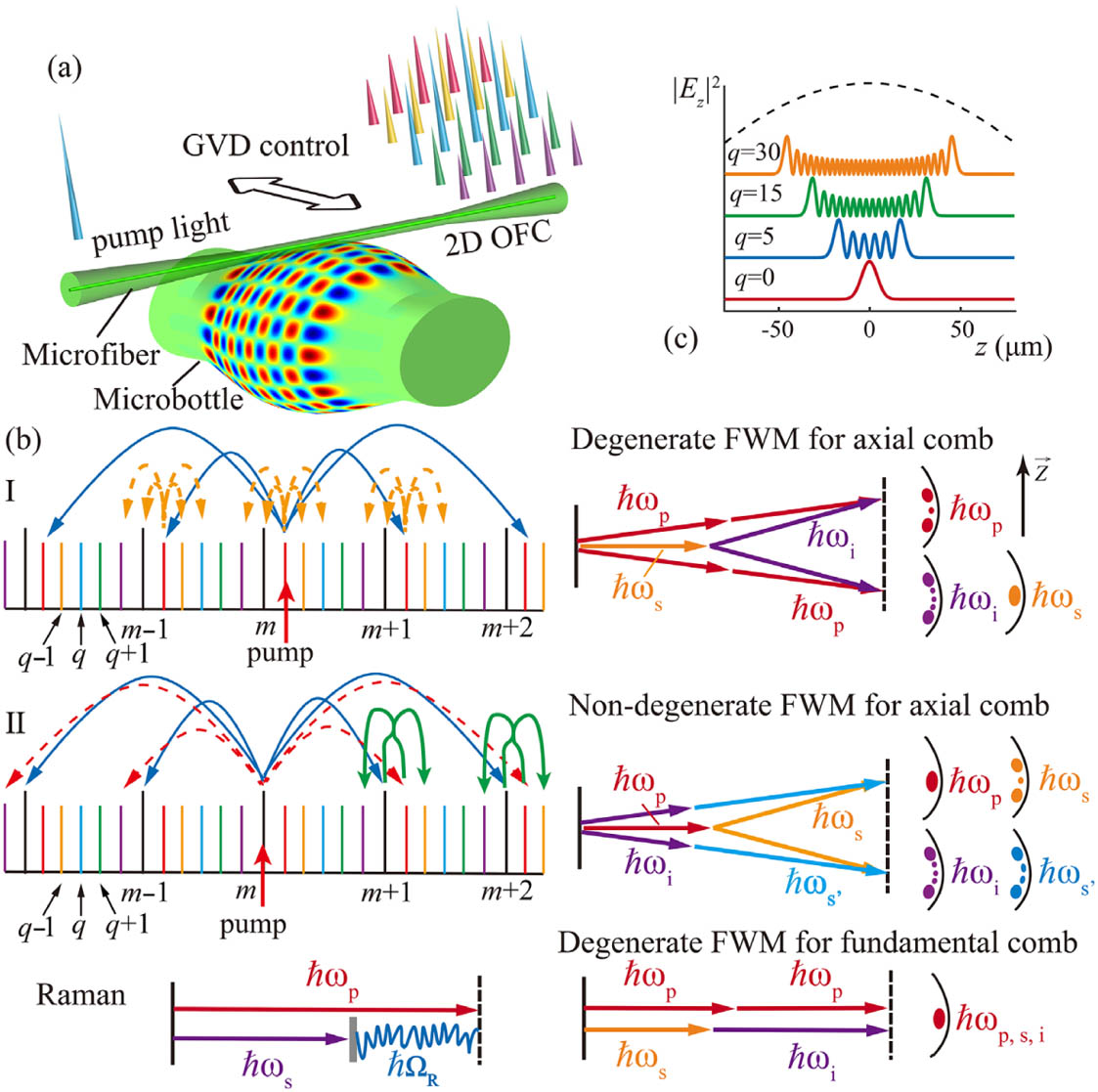
    Fig. 1. Experimental method and principle of proposed device. (a) Illustration of tunable 2D frequency comb generation principle. The blue comb lines represent the fundamental combs, and the other comb lines indicate the axial combs. The black arrow denotes the GVD tailoring approach. (b) 2D wideband Kerr comb generation mechanisms of the FWM-based oscillation process with both axial and azimuthal modes involved. (I) Degenerate FWM oscillation for axial mode series; (II) non-degenerate FWM oscillation for axial mode series. Bottom: general principle for SRS and degenerate FWM for fundamental Kerr comb generation. (c) Characteristic axial field distributions of WGM powers in a bottle resonator.
    Fabrication process of the microbottle resonators. The inset on the right indicates the microscopic images of the microbottle during the process.
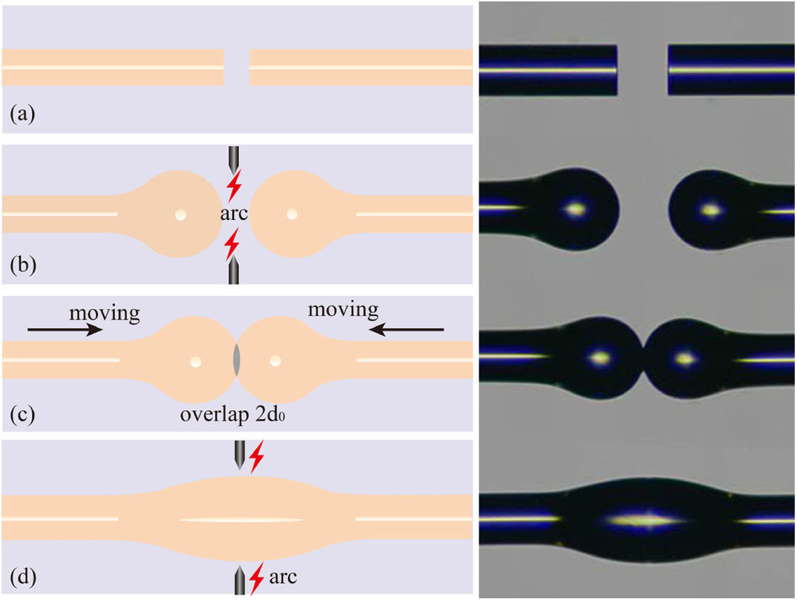
    Fig. 2. Fabrication process of the microbottle resonators. The inset on the right indicates the microscopic images of the microbottle during the process.
    (a) Experimental setup and device illustrating the optical frequency generation in bottle resonators. CW pump, continuous wave tunable pump source; EDFA, erbium-doped fiber amplifier; PC, polarization controller; PM, power meter; OSA, optical spectrum analyzer; ESA, signal and spectrum analyzer; OSC, digital storage oscilloscope; PD, photodetector; AFG, arbitrary function generator. (b)–(i) Experimental observation of eight primary Kerr combs exhibiting very different spacings of (b) 1/4-FSRm, (c) 1-FSRm, (d) 7/6-FSRm, (e) 5/4-FSRm, (f) 5/2-FSRm, (g) 7/2-FSRm, (h) 7-FSRm, and (i) 17/2-FSRm. The 2D Kerr comb spectrum is demonstrated in (a). The microfiber is placed at the bottle center [(d), inset] to excite the azimuthal and axial mode families.
    Fig. 3. (a) Experimental setup and device illustrating the optical frequency generation in bottle resonators. CW pump, continuous wave tunable pump source; EDFA, erbium-doped fiber amplifier; PC, polarization controller; PM, power meter; OSA, optical spectrum analyzer; ESA, signal and spectrum analyzer; OSC, digital storage oscilloscope; PD, photodetector; AFG, arbitrary function generator. (b)–(i) Experimental observation of eight primary Kerr combs exhibiting very different spacings of (b) 1/4-FSRm, (c) 1-FSRm, (d) 7/6-FSRm, (e) 5/4-FSRm, (f) 5/2-FSRm, (g) 7/2-FSRm, (h) 7-FSRm, and (i) 17/2-FSRm. The 2D Kerr comb spectrum is demonstrated in (a). The microfiber is placed at the bottle center [(d), inset] to excite the azimuthal and axial mode families.
    Comparison between experimental and simulated spectra along with the GVD dispersion curves: dispersion engineering and controllable Raman–Kerr transition. (a)–(c) The 2D Kerr combs excitation in the anomalous dispersion regime when the silica bottle resonator (Device 1, Δk=0.003056 μm−1) was excited at the center. (d)–(f) Raman–Kerr comb excitation in the weak normal dispersion regime when the silica bottle resonator (Device 1) was excited at 78 μm from center. (g)–(i) Raman–Kerr comb excitation in the anomalous dispersion regime when the silica bottle resonator (Device 2, Δk=0.003771 μm−1) was excited at the bottle center. (j)–(l) Raman lasing excitation in the strongly normal dispersion regime when the silica bottle resonator (Device 3, Δk=0.004041 μm−1) was excited at 96 μm from center. Corresponding numerical simulation for (b), (e), (h), and (k) with the same detuning δ=−5.4×10⁻⁸. (m) Magnified view of aperiodic hyperparametrical oscillations observed in (d). Inset A: magnified view of the comb spectrum from 1476 to 1520 nm. Inset B: magnified view of the comb spectrum from 1588 to 1610 nm. The peak widths of the comb lines are limited by the resolution and sampling points of the OSA.
    Fig. 4. Comparison between experimental and simulated spectra along with the GVD dispersion curves: dispersion engineering and controllable Raman–Kerr transition. (a)–(c) The 2D Kerr combs excitation in the anomalous dispersion regime when the silica bottle resonator (Device 1, Δk=0.003056  μm1) was excited at the center. (d)–(f) Raman–Kerr comb excitation in the weak normal dispersion regime when the silica bottle resonator (Device 1) was excited at 78 μm from center. (g)–(i) Raman–Kerr comb excitation in the anomalous dispersion regime when the silica bottle resonator (Device 2, Δk=0.003771  μm1) was excited at the bottle center. (j)–(l) Raman lasing excitation in the strongly normal dispersion regime when the silica bottle resonator (Device 3, Δk=0.004041  μm1) was excited at 96 μm from center. Corresponding numerical simulation for (b), (e), (h), and (k) with the same detuning δ=5.4×10⁸. (m) Magnified view of aperiodic hyperparametrical oscillations observed in (d). Inset A: magnified view of the comb spectrum from 1476 to 1520 nm. Inset B: magnified view of the comb spectrum from 1588 to 1610 nm. The peak widths of the comb lines are limited by the resolution and sampling points of the OSA.
    (a) Transition between FWM oscillation and Raman oscillation in a bottle resonator with decreasing pump detuning from top to bottom. State (i): when the pump is largely blue-detuned, the Kerr comb with 5/4-FSR spacing is obtained; state (ii): when the detuning is decreased, the Kerr comb broadens, and the single Raman line starts; state (iii): when the pump is further decreased, the Kerr comb lines disappear, and only the Raman-assisted comb exists; state (iv): when the detuning is at its smallest, the Raman comb vanishes, and a 7/2-FSR Kerr comb starts. (b) RF spectra corresponding to state (ii) and state (iv) in (a). (c) Transmission measurement of the bottle resonator at ∼1567 nm. The laser is tuned into the resonance with an increasing wavelength.
    Fig. 5. (a) Transition between FWM oscillation and Raman oscillation in a bottle resonator with decreasing pump detuning from top to bottom. State (i): when the pump is largely blue-detuned, the Kerr comb with 5/4-FSR spacing is obtained; state (ii): when the detuning is decreased, the Kerr comb broadens, and the single Raman line starts; state (iii): when the pump is further decreased, the Kerr comb lines disappear, and only the Raman-assisted comb exists; state (iv): when the detuning is at its smallest, the Raman comb vanishes, and a 7/2-FSR Kerr comb starts. (b) RF spectra corresponding to state (ii) and state (iv) in (a). (c) Transmission measurement of the bottle resonator at 1567  nm. The laser is tuned into the resonance with an increasing wavelength.
    (a) Calculated dispersion of silica bottle microresonators with fundamental modes q=0 for three different resonator radii. (b) Dispersion versus the maximum radius of the microbottle resonator for different axial modes q=0, q=30, and q=60. (c) Calculated ZDW of sample 1 as a function of axial mode numbers q. (d)–(f) Dispersion curves as a function of axial modes q and wavelength for different axial curvatures (d) Δk=0.003056 μm−1, (e) Δk=0.003771 μm−1, and (f) Δk=0.004041 μm−1.
    Fig. 6. (a) Calculated dispersion of silica bottle microresonators with fundamental modes q=0 for three different resonator radii. (b) Dispersion versus the maximum radius of the microbottle resonator for different axial modes q=0, q=30, and q=60. (c) Calculated ZDW of sample 1 as a function of axial mode numbers q. (d)–(f) Dispersion curves as a function of axial modes q and wavelength for different axial curvatures (d) Δk=0.003056  μm1, (e) Δk=0.003771  μm1, and (f) Δk=0.004041  μm1.
    Simulated spectrum and temporal profile (insets) for generated combs in silica bottle resonators with 402 GHz FSR pumping at 1551 nm for phase detuning of (a) −0.05, (b) −0.002, (c) −0.001, and (d) −5.4×10⁻⁸ from cold-cavity resonance.
    Fig. 7. Simulated spectrum and temporal profile (insets) for generated combs in silica bottle resonators with 402 GHz FSR pumping at 1551 nm for phase detuning of (a) 0.05, (b) 0.002, (c) 0.001, and (d) 5.4×10⁸ from cold-cavity resonance.
    Xueying Jin, Xin Xu, Haoran Gao, Keyi Wang, Haojie Xia, Liandong Yu. Controllable two-dimensional Kerr and Raman–Kerr frequency combs in microbottle resonators with selectable dispersion[J]. Photonics Research, 2021, 9(2): 171
    Download Citation