We report a broadband two-dimensional (2D) Kerr and Raman–Kerr frequency comb generation in a silica bottle resonator accounting for azimuthal and axial degrees of freedom and pioneer a method that allows for controlled and reversible switching between a four wave mixing (FWM) state and a stimulated Raman scattering state. The repetition rate of the Raman–Kerr comb is not an integer number of the free spectral range, which spans more than 242 nm with hundreds of teeth. We show that, experimentally and numerically, multiple 2D comb regimes can be selectively accessed via dispersion engineering by exciting different orders of axial modes or modifying the curvature of the axial profile, involving cascaded FWM, Raman lasing, and Raman-assisted FWM. The effect of axial curvature on dispersion is associated with the axial mode number in bottle resonators. Our approach enables dispersion and spectral engineering flexibility in any resonator with localized axial modes.
1. INTRODUCTION
Optical frequency comb (OFC) generation in ultrahigh-Q whispering gallery mode (WGM) microcavities, denoted as microcombs [1,2], has attracted a broad spectrum of interests in science and technology, such as low-threshold microlasers, atomic clocks [3], and precision spectroscopy owing to their flexible repetition rate, wide bandwidth, and compact size. The exceptionally long photon lifetime (μ) and small modal volume () enhance the light–matter interaction, which enables us to realize intracavity nonlinear frequency conversions with a low parametric oscillation threshold and broad bandwidth. In the case of a silica whispering gallery mode resonator (WGMR), the leading nonlinear effects, i.e., the third-order nonlinearities such as four-wave mixing (FWM), stimulated Raman scattering (SRS), and stimulated Brillouin scattering are observed and investigated [4,5]. In this regard, light–matter interaction in a continuous-wave (cw) pumped microcavity may initiate either a Kerr comb or Raman comb, as the Brillouin scattering frequency is more difficult to overlap with the resonant frequency. Specifically, the Kerr comb is related to Kerr nonlinearity induced optical parametric oscillation arising from the quasi-instantaneous electronic response of the medium to pump excitation; whereas the Raman comb, a fundamental inelastic scattering process, originates from the interaction between light and molecular vibrations. The interplay between the Kerr and Raman combs in microcavities has attracted great interest in recent years, and the application of SRS to comb generation has potential in fruitful fields such as Raman lasing [6,7], sensing, and self-frequency shift devices [2]. A central challenge in this area is selective excitation of the Kerr comb and Raman comb in a nonlinear WGM microcavity in regards to finding a convenient method to enhance or suppress the Raman process.
There have been promising efforts to achieve transitions between the Kerr comb state and the Raman oscillation state by designing the resonator size/free spectral range (FSR) [8,9], changing the pump power or laser-cavity detuning [10], adjusting the coupling gap [11], or optimizing the group velocity dispersion (GVD) through varying the wall thickness of bubble resonators [12]. However, geometrical control needs a high degree of controllability in the fabrication process, and the geometrical parameters are difficult to modify in practical applications once the microcavity is fabricated. As for silica microbottle resonators, the transition between a Kerr comb state and Raman oscillation state is more difficult due to their broad Raman line width and dense mode spectrum, compared to the case in SiN, AlN, or silica microspheres. In this regard, alignment between the cavity resonance and the Stokes line may be impractical.
In this work, we present a convenient and simple approach to selectively accessing the parametric and/or Raman oscillation state without modification of resonator geometry based on the ultrahigh-Q silica microbottle platform. A controlled and reversible transition between modulation instability (MI) and Raman oscillation is realized by selectively exciting localized axial modes, designing the axial profile of the device, or adjusting the pump detuning. This Kerr–Raman competition is well described and analyzed by numerical simulations based on the generalized Lugiato–Lefever (L-L) equation, with the Raman effect included, which give important insights into the interplay between axial mode numbers and bottle axial curvature on dispersion. Moreover, wideband two-dimensional (2D) Kerr and Raman–Kerr frequency combs are experimentally demonstrated with a repetition rate smaller than one FSR. Our study provides a route for efficient Raman lasing and sensing applications in a silica microcavity and may be a critical step towards 2D frequency comb generation [13] in microcavity devices.
Sign up for Photonics Research TOC. Get the latest issue of Photonics Research delivered right to you!Sign up now
2. EXPERIMENTAL PRINCIPLE AND METHOD
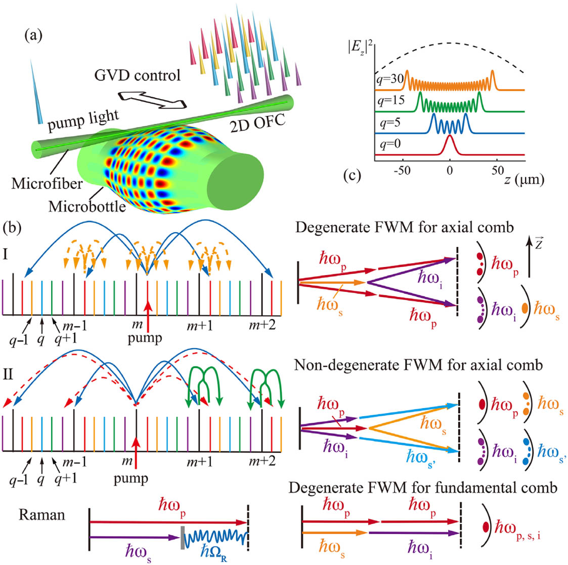
Figure 1.Experimental method and principle of proposed device. (a) Illustration of tunable 2D frequency comb generation principle. The blue comb lines represent the fundamental combs, and the other comb lines indicate the axial combs. The black arrow denotes the GVD tailoring approach. (b) 2D wideband Kerr comb generation mechanisms of the FWM-based oscillation process with both axial and azimuthal modes involved. (I) Degenerate FWM oscillation for axial mode series; (II) non-degenerate FWM oscillation for axial mode series. Bottom: general principle for SRS and degenerate FWM for fundamental Kerr comb generation. (c) Characteristic axial field distributions of WGM powers in a bottle resonator.
We propose two mechanisms to generate 2D frequency combs: (i) by employing degenerate FWM only [method I in Fig. 1(b)] and (ii) by combining degenerate FWM and non-degenerate FWM [method II in Fig. 1(b)]. It is worth noting that the FWM for axial combs includes redistribution of photon momentum along the bottle axis () in comparison to the fundamental comb case, which leads to different spatial distributions of comb modes. Routine FWM, including only the fundamental mode family, is also presented in the lower panel of Fig. 1(b) for comparison. It is seen that the mode fields are located in the vicinity of the equatorial plane of the resonator without the conversion of photon momentum along the resonator axis () in the FWM process. Besides, the generation principle of SRS is also presented in the bottom left panel of Fig. 1(b). Figure 1(c) displays the axial distribution of the WGMs power for the quantum numbers , 5, 15, 30. The WGMs in the bottle resonator are characterized by three mode numbers (, , ), and , , and indicate the azimuthal, radial, and axial quantum number, respectively. It is shown that this axial standing wave is greatly enhanced around the turning points of the harmonic motion. To effectively generate broadband 2D frequency combs, the axial mode eigenfrequencies have to match the azimuthal mode eigenfrequencies in a bottle resonator. Thus, the axial curvature should be carefully modified.
Figure 2.Fabrication process of the microbottle resonators. The inset on the right indicates the microscopic images of the microbottle during the process.
Figure 3.(a) Experimental setup and device illustrating the optical frequency generation in bottle resonators. CW pump, continuous wave tunable pump source; EDFA, erbium-doped fiber amplifier; PC, polarization controller; PM, power meter; OSA, optical spectrum analyzer; ESA, signal and spectrum analyzer; OSC, digital storage oscilloscope; PD, photodetector; AFG, arbitrary function generator. (b)–(i) Experimental observation of eight primary Kerr combs exhibiting very different spacings of (b) , (c) , (d) , (e) , (f) , (g) , (h) , and (i) . The 2D Kerr comb spectrum is demonstrated in (a). The microfiber is placed at the bottle center [(d), inset] to excite the azimuthal and axial mode families.
To generate wideband 2D Kerr combs, the microfiber was firstly excited at the center of a bottle resonator with μ, μ, and μ, as shown in Fig. 3. In this case, both of the basic mode and axial mode sequences can be excited [16,17] under an anomalous regime (see Section 4 for theoretical verification). The shape of the microbottle was fitted with parabolic profile , where is the maximal radius at , and indicates the axial curvature of the profile. We adjusted the cavity loading by scanning the coupling microfiber along the bottle axis, measured the parametric oscillation threshold, and finely tuned the pump wavelength so that the pump can be self-thermally locked to a certain WGM. During the measurement process, the coupling microfiber was always in physical contact with the bottle resonator to ensure the coupling stability. Figure 3 presents the measured transmitted optical spectra for the different identified Kerr comb patterns, corresponding to , , , , , , , and of the bottle resonator, respectively. Here, is the azimuthal FSR of the resonator. The “Type I” [18] fundamental comb with sidebands separated by one azimuthal FSR was realized [Fig. 3(c)], and, by tuning the pump wavelength, the “Type II” comb with multimode spaced lines was also verified [Fig. 3(h)]. It is seen from Fig. 3(c) that the first-order signal–idler photons are symmetrically located with respect to the pump with the spacing of 3.24 nm, which is in good agreement with the calculated []. Different primary comb spacings use the same pump power, since different radial mode families are excited simultaneously in the resonator, and the energy conservation condition is met for these modes. The detuning between the pump and resonance may induce the variations of comb spacing, but the effect is limited owing to the on-resonance requirement. In our experiment, we observed a ratio of less than two when changing the detuning parameter. Thus, the geometrical dispersion difference is responsible for this observation. We attribute the above two types of fundamental combs to degenerate FWM [lower right panel of Fig. 1(b)], as no Raman oscillation signal is observed. Note that the pump wavelengths in Fig. 3 are larger than the zero dispersion wavelength (ZDW) of Bottle 1 [1531 nm see Section 5] and thus correspond to the anomalous dispersion regime for .
It is interesting to find that the repetition rate of the comb is not an integral multiple of the fundamental FSR in some cases, as shown in Figs. 3(d)–3(g), 3(i), and 3(b). For example, in Fig. 3(b), a broadband comb spaced by can be generated, which is simultaneously initiated at the axial and azimuthal eigenfrequencies. The low repetition frequency axial comb lines match a series of equidistant axial eigenfrequencies and are localized between adjacent azimuthal comb series. The FSR of the wideband azimuthal mode series is exactly four times the FSR of the narrowband axial mode series [, the calculated value ]. Such a comb is termed a 2D frequency comb by taking into account dynamics in the azimuthal and axial directions with different orbital momenta, which was theoretically predicted in Refs. [13,19]. Additionally, the frequency comb with spacing is also excited by degenerate FWM [Fig. 3(e)]. Therefore, the generation of comb lines may be ascribed to the cascaded non-degenerate FWM between the mode series and the series [mechanism II in Fig. 1(b)]. Besides the and its integer multiples mode series, there is also the series that is excited, as shown in Fig. 3(d). This may be explained similar to the case of the series, but belongs to the family of modes with different radial quantum number .
4. DISPERSION ENGINEERING AND CONTROLLED RAMAN–KERR TRANSITION
Figure 4.Comparison between experimental and simulated spectra along with the GVD dispersion curves: dispersion engineering and controllable Raman–Kerr transition. (a)–(c) The 2D Kerr combs excitation in the anomalous dispersion regime when the silica bottle resonator (Device 1, μ) was excited at the center. (d)–(f) Raman–Kerr comb excitation in the weak normal dispersion regime when the silica bottle resonator (Device 1) was excited at 78 μm from center. (g)–(i) Raman–Kerr comb excitation in the anomalous dispersion regime when the silica bottle resonator (Device 2, μ) was excited at the bottle center. (j)–(l) Raman lasing excitation in the strongly normal dispersion regime when the silica bottle resonator (Device 3, μ) was excited at 96 μm from center. Corresponding numerical simulation for (b), (e), (h), and (k) with the same detuning . (m) Magnified view of aperiodic hyperparametrical oscillations observed in (d). Inset A: magnified view of the comb spectrum from 1476 to 1520 nm. Inset B: magnified view of the comb spectrum from 1588 to 1610 nm. The peak widths of the comb lines are limited by the resolution and sampling points of the OSA.
Figure 4(g) shows a Raman-assisted Kerr comb with an identical spacing of 1/4-FSR. It was realized by switching to another bottle resonator with a different axial profile (Device 2, μ) for pumping. This broadband spectrum is formed by the initial Raman scattering and the subsequent non-degenerate FWM process. The SRS has a broad bandwidth gain of more than 40 THz in silica, which is much larger than (0.40 THz) and (0.10 THz) of the bottle resonator. As a result, more than 86 Kerr comb lines arise near the pump, and 29 Raman comb lines occur in the Raman waveband. We found that the Stokes components are not a single Raman lasing but a series of comb lines spaced by one [left inset in Fig. 4(g)]. To the best of our knowledge, this is the first experimental observation of a 2D Raman–Kerr comb that simultaneously excites the axial and azimuthal components. One expects that the transition process is determined by the cavity GVD, circulating power (pump detuning), and polarization state of the pumped mode. For low modes, variation of has little influence on the cavity dispersion [Figs. 4(c) and 4(i)]. Thus, the transition from an FWM state to a Raman–Kerr state in Fig. 4(g) may be explained by the excitation of modes with different polarizations [10]. By further excitation of higher-order axial modes in a bottle with more pronounced axial profile (Device 3, μ), we also observed Raman lasing in a strongly normal GVD regime. Figure 4(j) describes a multimode Raman lasing spectrum with nearly no FWM, which verifies a simple and convenient method for mode dispersion management. Note that the changing of axial profile works only for large axial mode numbers (see Section 5 for detail). Figure 4 offers insightful understanding of the GVD effect on the formation of Raman–Kerr combs. Our results suggest that three distinct regimes can be selectively accessed via dispersion engineering by excitation of different axial modes, designing a proper axial profile, as well as adjusting the polarization state.
Figure 5.(a) Transition between FWM oscillation and Raman oscillation in a bottle resonator with decreasing pump detuning from top to bottom. State (i): when the pump is largely blue-detuned, the Kerr comb with 5/4-FSR spacing is obtained; state (ii): when the detuning is decreased, the Kerr comb broadens, and the single Raman line starts; state (iii): when the pump is further decreased, the Kerr comb lines disappear, and only the Raman-assisted comb exists; state (iv): when the detuning is at its smallest, the Raman comb vanishes, and a 7/2-FSR Kerr comb starts. (b) RF spectra corresponding to state (ii) and state (iv) in (a). (c) Transmission measurement of the bottle resonator at . The laser is tuned into the resonance with an increasing wavelength.
To gain more physical insight into the tunable Raman–Kerr combs generated in bottle resonators, we analyzed the dispersion engineering and Kerr–Raman transition process utilizing our theoretical models. Kerr combs initiated in a bottle resonator mainly involve two different families of WGMs: the azimuthal mode series with spacing of one FSR, , and the axial mode series with spacing. Here, we focus on the dispersion tailoring based on these longitudinal FSR spaced WGMs. The total dispersion in a bottle resonator consists of two contributions: that is the material dispersion and geometry dispersion . The geometrical dispersion is interpreted as the variation of the FSR and can be calculated via an approximation of the eigenfrequencies of bottle resonators. The resonance frequency of bottle microresonator modes with a harmonic profile is given by [23] where , is the th root of the Airy function for different radial modes, which is equal to 2.338, 4.088, and 5.521 for , 2, 3, respectively, and . and indicate the axial curvature and maximum radius of a bottle resonator. is the azimuthal mode number, and denotes the axial mode number. is the speed of light in vacuum, and denotes the refractive index of the material. Hence, the FSR and geometrical dispersion can be calculated from the resonator eigenfrequencies as follows [24]:
On the other hand, the material dispersion is proportional to the material GVD and can be expressed as ; here, , which can be solved numerically by exploiting the Sellmeier equations. The total dispersion, which takes into account geometrical dispersion as well as material dispersion, can therefore be expressed as We then converted into the widely used second-order dispersion by applying the approximated expression [25]
Figure 6(a) shows the calculated total dispersion as a function of wavelength for silica bottle resonators with axial mode number . We study three bottles with different maximum radii of μ, μ, and μ. Larger diameters offer a flattening of the dependence of FSR on the wavelength. Specifically, the dispersion of sample 1 increases from to 3.51 MHz within the waveband of 1.4–1.7 μm, whereas, for sample 2 and sample 3, this value changes from to 3.10 MHz and to 2.83 MHz, respectively. The flat dispersion is critical for a wideband frequency comb generation. Additionally, the ZDW shifts to a shorter wavelength with an increased diameter [see inset in Fig. 6(a)]. Figure 6(b) plots the dispersion for different dimensions of bottle resonators at a wavelength of 1550 nm. It is seen that larger bottle sizes increase the dispersion for a fixed . For fundamental mode family , the anomalous dispersion occurs when the size of the resonator exceeds 75 μm. At the radius of 81.9 μm [vertical black dashed line in Fig. 6(b), Device 1], the total dispersion for and is in the anomalous regime (), while for is in the normal dispersion regime (). This provides a convenient and flexible scheme for dispersion and ZDW adjustment without modifying the resonator geometry. Experimentally, this can be implemented simply by adjusting the axial coupling positions of the microfiber. For example, the fundamental mode is excited when the coupling fiber is positioned at , and the axial mode can be initiated when the microfiber is moved 45.2 μm away from the center (at the caustic of bottle modes), which can be obtained by calculating axial mode field distributions of the bottle resonator [17]. Indeed, to ensure that the 2D modes, including the azimuthal and axial series, are excited in the bottle, the central excitation position is preferable. To further confirm the GVD adjustment depending on axial mode number , we provided the calculated ZDW when is increased from 0 to 190, as shown in Fig. 6(c). Specifically, ZDW alters from 1531 to 1809 nm with an increase of from 0 to 150, suggesting a simple and large-scale ZDW and GVD engineering approach. This interesting characteristic may push the ZDW of silica towards the mid-infrared (mid-IR) range and is favorable for broadband Kerr comb generation in this waveband.
Figure 6.(a) Calculated dispersion of silica bottle microresonators with fundamental modes for three different resonator radii. (b) Dispersion versus the maximum radius of the microbottle resonator for different axial modes , , and . (c) Calculated ZDW of sample 1 as a function of axial mode numbers . (d)–(f) Dispersion curves as a function of axial modes and wavelength for different axial curvatures (d) μ, (e) μ, and (f) μ.
We next study the relationship between GVD and resonator axial curvature and demonstrate an additional degree of freedom to control the dispersion in bottle resonators. Figures 6(d)–6(f) show the calculated dispersion for three bottles with different axial curvatures (Devices 1–3) but approximately the same radii as a function of axial mode number and wavelength. It is found that the GVD does not change significantly for smaller modes. Nevertheless, for higher modes, the dispersion becomes larger with an increased . There exists a point (by selecting an appropriate axial mode ) at which the bottle exhibits a weak flattened normal dispersion, and the GVD value at this point can be tuned by choosing the bottle axial profile. From the above discussions, we can conclude that the total dispersion in a bottle resonator can be managed by selecting different axial modes and axial profile curvatures, and the interplay between these two effects should be considered. Compared to the dispersion control method in the microbubble [26], which can be realized by designing the diameter and wall thickness, the bottle resonator provides a post fabrication dispersion management scheme without changing the resonator geometry.
Based on the above dispersion analysis, we introduce the generalized L-L equation, with SRS taken into account, to model and analyze the Kerr–Raman transition dynamics. The generalized L-L equation is given as The second and third terms on the left side describe the Kerr and Raman effects, respectively. Here, is the envelope of the intracavity field, and are the slow time and fast time, respectively, refers to the roundtrip time, is the cavity length, and indicate the intrinsic loss and external coupling coefficient, respectively, accounts for the pump phase detuning, represents the GVD, denotes the nonlinear coefficient, and refers to the pump power. is the Raman fractional response for silica, , and indicates the Raman response function. In our simulations, the Raman effect is calculated in the frequency domain with a Lorentzian lineshape of central frequency and bandwidth [27]. To simulate the experimentally exploited device, we choose , μ, , , , and . Numerical simulations were performed by solving Eq. (5) with split-step Fourier algorithm [28]. The wavelength-dependent dispersion is taken into account within the Fourier term. The GVD curves on the right column of Fig. 4 were calculated by solving Eqs. (1)–(4) and extracted from Figs. 6(d)–6(f).
Figure 4 (second and third columns) shows the simulation results of multiple different regimes involving the Kerr comb, Raman–Kerr comb, and Raman comb generation. The switching between three distinct regimes was realized via dispersion engineering just by adjusting the coupling positions of the microfiber along the bottle axis or choosing different axial curvatures. We first excited Device 1 (μ) at the bottle center, which exhibits a weak anomalous dispersion. As seen in Fig. 4(b), a stable Kerr comb spectrum appears as we expected. This corresponds to a Turing pattern regime or primary comb [29], which originates from the cascaded FWM process at a 1-FSR spacing. Note that no Raman comb lines were observed, suggesting that the FWM comb is dominant in this state. Then, we moved the coupling microfiber 78 μm away from the bottle center and observed the output spectrum [Fig. 4(e)]. The excitation of the axial mode pushes the resonator to a weak normal dispersion regime. It is found that both Kerr and Raman combs are simultaneously excited in this regime. Next, we switched to a bottle resonator with larger axial curvature (Device 2, μ) and excited it at the bottle center (). Figure 4(h) displays a spectrum where Raman-assisted non-degenerate FWM has been initiated in the resonator. It was realized by pumping another WGM resonance with a different polarization state [6]. The results further confirm that both Kerr and Raman effects can be generated under anomalous dispersion once the pump power exceeds the Raman threshold. Distinct from the weak normal GVD case, the Raman oscillation without FWM is observed in simulations with a strongly normal dispersion regime. This was generated when Device 3 (μ) was excited at 96 μm away from the bottle center [Fig. 4(l)]. No appreciable Kerr combs were excited, and strong Raman lines were created at a frequency of red shifted from the pump. The absence of the Kerr comb in this case is the result of the strongly normal GVD, therefore rendering a negligible MI gain [30]. The Kerr–Raman transition behavior revealed by simulations is similar to our experimental observations. The differences between the experimental results and numerical results can be explained by the following two main reasons. First, the Q factor and the WGM density are different for various modes, thereby rendering different probabilities of optimal conditions for FWM oscillation in different modes. Second, mode coupling between different mode families and additional device loss in the system could increase the loss in our experiment. Our numerical results further confirm the feasibility of the dispersion management method in our bottle resonators.
Figure 7.Simulated spectrum and temporal profile (insets) for generated combs in silica bottle resonators with 402 GHz FSR pumping at 1551 nm for phase detuning of (a) , (b) , (c) , and (d) from cold-cavity resonance.
The 2D Kerr and Raman–Kerr combs presented here provide more degrees of freedom when compared with conventional frequency combs based on fundamental WGMs [5], and the bottle platform allows for better control of dispersion. Our method is also applicable for any resonator with axial/polar modes. However, the experimental demonstration of wideband 2D frequency combs involving both the axial and azimuthal mode series in a microcavity, although predicted by numerical simulations [33], has proven to be difficult. The first challenge is the much larger mode volume occupied by the bottle resonator. Hence, a higher Raman oscillation threshold is predicted in this case. Second, the axial modes are decoupled, and a large number of spatial overlapped modes are supported in the bottle resonator. This generates numerous avoided mode crossings that impede the formation of solitons in the cavity [34]. We also observed the measured transmission spectra of different resonances overlapping with each other in our experiment. Moreover, matching the axial lines with the azimuthal lines is difficult. Although it could be realized in the surface nanoscale axial photonics (SNAP) platform [35] with a delicate technique, the extremely large mode volume ( times larger than the conventional equatorial resonator) as well as the inevitable coupling and interference with the delocalized radiation modes [36] makes the initiation of the combs a great challenge. Therefore, in this work, we propose to exploit the non-degenerate FWM with axial WGMs included for generation of 2D Kerr frequency combs in bottle microresonators. This mechanism overcomes the relatively low MI gain close to the pump frequency similar to the parametric seeding method [37]. With the aid of a simple and convenient fabrication technique, the axial series are brought to match the azimuthal mode series such that the wideband 2D frequency combs are created.
In summary, we have experimentally and theoretically validated an approach for generation of controllable 2D Kerr and Raman–Kerr frequency combs in a high-Q bottle resonator platform. The gain transition between FWM and SRS-dominant states can be achieved in a controllable and reversible way via dispersion management by adjusting the axial coupling position of the microfiber (axial mode ) or axial curvature of the bottle resonator (). In particular, the effect of axial mode number and bottle axial curvature on the GVD couples with each other in the bottle resonator. Notably, broadband 2D Kerr and Raman–Kerr frequency combs with spans of 114 and 242 nm were realized for the first time, to the best of our knowledge, by simultaneous excitation of axial and azimuthal mode sequences (). These interesting 2D frequency combs can extend from hundreds to thousands of comb lines with flexible repetition rates and could find applications for future precision spectroscopy and optical clocks in both telecommunication and mid-IR spectral ranges.
Acknowledgment
Acknowledgment. We thank Dr. Rui Niu from the University of Science and Technology of China for helpful discussions.