• Laser & Optoelectronics Progress
  • Vol. 57, Issue 2, 21106 (2020)
Pang Zhengya1, Zhou Zhifeng1、*, Wang Liduan2, and Ye Juelei1
Author Affiliations
  • 1College of Mechanical and Automotive Engineering, Shanghai University of Engineering Science, Shanghai 201620, China
  • 2Shanghai Compass Satellite Navigation Technology Co. Ltd., Shanghai 201801, China
  • show less
    DOI: 10.3788/LOP57.021106 Cite this Article Set citation alerts
    Pang Zhengya, Zhou Zhifeng, Wang Liduan, Ye Juelei. Motion Compensation Method Based on Lidar[J]. Laser & Optoelectronics Progress, 2020, 57(2): 21106 Copy Citation Text show less
    Schematic of laser radar scanning a circle
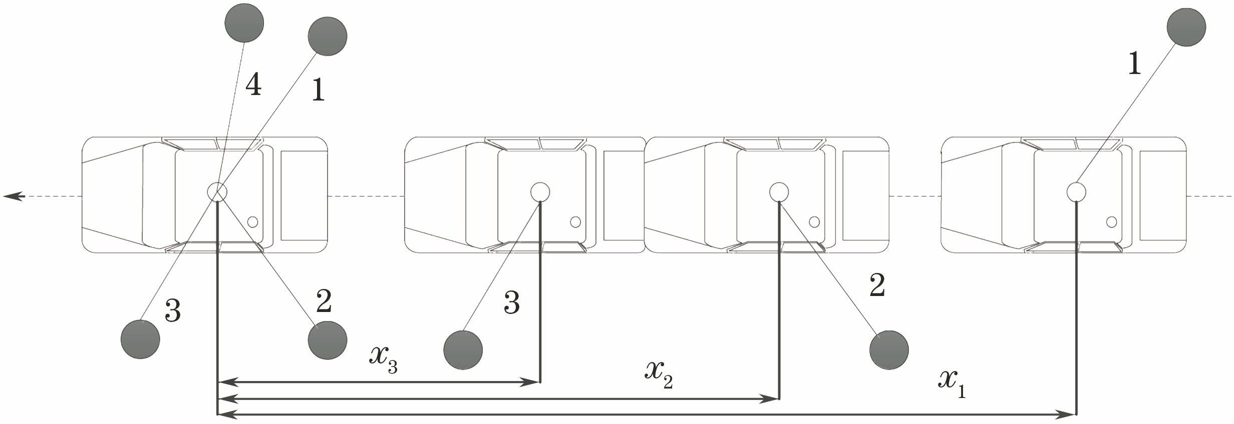
    Fig. 1. Schematic of laser radar scanning a circle
    Schematics of vehicle body coordinate transformation. (a) Translational motion of vehicle body; (b) rotation motion of vehicle body
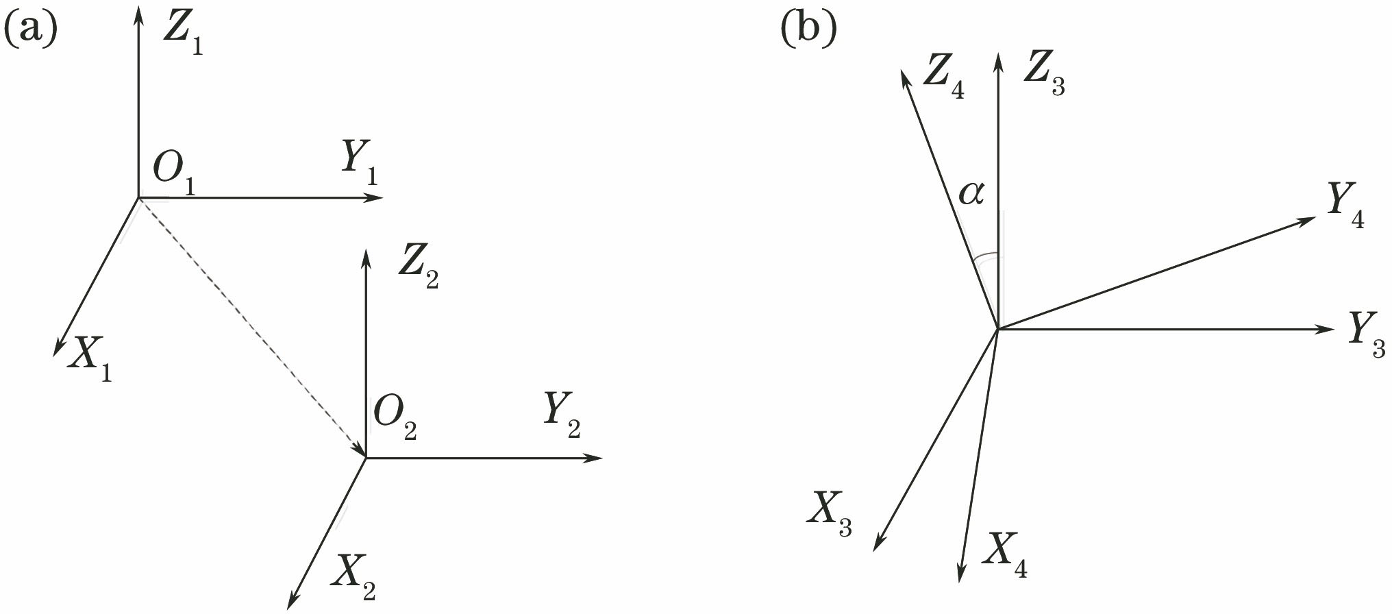
    Fig. 2. Schematics of vehicle body coordinate transformation. (a) Translational motion of vehicle body; (b) rotation motion of vehicle body
    Spatial description of quaternion relative to reference coordinate system
    Fig. 3. Spatial description of quaternion relative to reference coordinate system
    Flow chart of improved motion compensation algorithm
    Fig. 4. Flow chart of improved motion compensation algorithm
    Improved lidar motion compensation pseudo-code based on Gaussian mixture model
    Fig. 5. Improved lidar motion compensation pseudo-code based on Gaussian mixture model
    Lidar installation and experimental equipment
    Fig. 6. Lidar installation and experimental equipment
    Original point cloud data
    Fig. 7. Original point cloud data
    Point cloud data after motion compensation
    Fig. 8. Point cloud data after motion compensation
    Motion compensation results when vehicle turns at traffic intersection
    Fig. 9. Motion compensation results when vehicle turns at traffic intersection
    Motion compensation results when vehicle enters the motion compensation area
    Fig. 10. Motion compensation results when vehicle enters the motion compensation area
    MethodAdvantageDisadvantage
    Euler anglesmethodOnly three differential equations(three independent parameters) are required;it is directly initialized by pitch, yaw, and roll angleNonlinear differential equation;there is no singular value at ±90°;the order of rotation is important
    Direction cosinemethodLinear equation;no singular value;the direction of thetransformation matrix is solvedSix independent differential equations;complex computation;Euler angles can not be obtained directly
    The quaternionmethodThere are only four differential equations;no singular values and easy solutions;the way only need three differentialequations (three independent parameters);it is directly initialized by pitch,yaw and roll angleEuler angle and transformationmatrix can not be obtained directly;the initial conditions forEuler angles must be used
    Table 1. Comparison of advantages and disadvantages of transformation matrix parameterization methods
    Pang Zhengya, Zhou Zhifeng, Wang Liduan, Ye Juelei. Motion Compensation Method Based on Lidar[J]. Laser & Optoelectronics Progress, 2020, 57(2): 21106
    Download Citation