• Opto-Electronic Engineering
  • Vol. 51, Issue 1, 230171-1 (2024)
Longfei Wang1、2, Yuwang Hu1、2, Zeguang Zhang1、2, Yue Liu1、2, and Changxi Xue1、2、*
Author Affiliations
  • 1School of Optoelectronic Engineering, Changchun University of Science and Technology, Changchun, Jilin 130022, China
  • 2Key Laboratory of Advanced Optical System Design and Manufacturing Technology of Universities of Jilin Province, Changchun University of Science and Technology, Changchun, Jilin 130022, China
  • show less
    DOI: 10.12086/oee.2024.230171 Cite this Article
    Longfei Wang, Yuwang Hu, Zeguang Zhang, Yue Liu, Changxi Xue. Rapid manufacturing technology for aspheric optical elements[J]. Opto-Electronic Engineering, 2024, 51(1): 230171-1 Copy Citation Text show less
    Process chains for manufacturing aspheric optical elements
    Fig. 1. Process chains for manufacturing aspheric optical elements
    PGM schematic diagram. (a) Heating stage; (b) Pressurizing stage; (c) Annealing stage; (d) Cooling stage
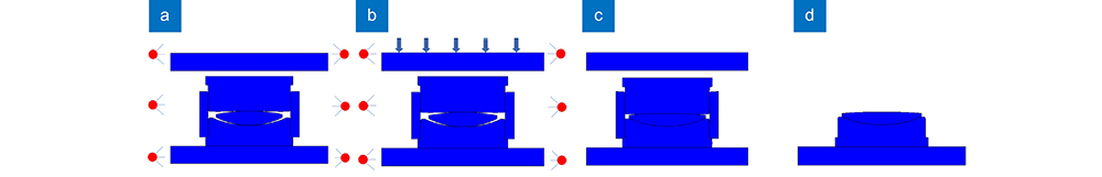
    Fig. 2. PGM schematic diagram. (a) Heating stage; (b) Pressurizing stage; (c) Annealing stage; (d) Cooling stage
    Optical glass materials[15]. (a) Optical glass blanks; (b) HWS series sulfur-based infrared glass; (c) Precision glass molded aspheric lenses
    Fig. 3. Optical glass materials[15]. (a) Optical glass blanks; (b) HWS series sulfur-based infrared glass; (c) Precision glass molded aspheric lenses
    Mold materials for molding technology[16]. (a) Tungsten carbide material; (b) Microcrystalline aluminum material
    Fig. 4. Mold materials for molding technology[16]. (a) Tungsten carbide material; (b) Microcrystalline aluminum material
    Single point diamond turning process[20]. (a) Single point diamond turning; (b) Moulding concave core; (c) Moulding convex surface
    Fig. 5. Single point diamond turning process[20]. (a) Single point diamond turning; (b) Moulding concave core; (c) Moulding convex surface
    Glass molding simulation[25]. (a) Heating of glass preforms and molds to a molding temperature of 700℃; (b) Molding of preforms at constant temperature; (c) Annealing of molded lenses
    Fig. 6. Glass molding simulation[25]. (a) Heating of glass preforms and molds to a molding temperature of 700℃; (b) Molding of preforms at constant temperature; (c) Annealing of molded lenses
    Refractive index change distributions of P-SK57 glass cylinder and P-LASF47 glass cylinder cooled at different rates[25]
    Fig. 7. Refractive index change distributions of P-SK57 glass cylinder and P-LASF47 glass cylinder cooled at different rates[25]
    Temperature distributions of glass preforms at different heating times[31]. (a) 120 s; (b) 180 s; (c) 220 s
    Fig. 8. Temperature distributions of glass preforms at different heating times[31]. (a) 120 s; (b) 180 s; (c) 220 s
    Stress-strain diagram in conventional glass forming distribution[32]. (a) Stress distribution; (b) Strain distribution diagram
    Fig. 9. Stress-strain diagram in conventional glass forming distribution[32]. (a) Stress distribution; (b) Strain distribution diagram
    Stress-strain diagram in two-step glass forming [32]. (a) Stress distribution; (b) Strain distribution diagram
    Fig. 10. Stress-strain diagram in two-step glass forming [32]. (a) Stress distribution; (b) Strain distribution diagram
    Simulated stress results for molded lenses[33]. (a) Equivalent stress on the lens surface 1; (b) Shear stress σyzin the cross section
    Fig. 11. Simulated stress results for molded lenses[33]. (a) Equivalent stress on the lens surface 1; (b) Shear stress σyzin the cross section
    MATLAB plotted temperature clouds of the mold, core, and glass preforms[34]. (a) Initial temperature; (b) Final temperature
    Fig. 12. MATLAB plotted temperature clouds of the mold, core, and glass preforms[34]. (a) Initial temperature; (b) Final temperature
    Temperature clouds of the mold, core, and glass preforms plotted by MSC.Marc software[34]. (a) Initial temperature; (b) Final temperature
    Fig. 13. Temperature clouds of the mold, core, and glass preforms plotted by MSC.Marc software[34]. (a) Initial temperature; (b) Final temperature
    Development of precision glass molding technology
    Fig. 14. Development of precision glass molding technology
    Adhesion of sulfide glass to the surface of a mold coated with Re-Ir[42]. (a) Mold surface before molding; (b) The surface of the mold after molding at 330 ℃ ; (C) The surface of the mold after molding at 340 ℃
    Fig. 15. Adhesion of sulfide glass to the surface of a mold coated with Re-Ir[42]. (a) Mold surface before molding; (b) The surface of the mold after molding at 330 ℃ ; (C) The surface of the mold after molding at 340 ℃
    Results of cylindrical glass molding at molding temperatures between 352 ℃ and 392 ℃ and pressures of 1362 N[49]
    Fig. 16. Results of cylindrical glass molding at molding temperatures between 352 ℃ and 392 ℃ and pressures of 1362 N[49]
    Surface images of molded sulfur-based glass lenses[50]. (a) Lens 1; (b) Lens 2
    Fig. 17. Surface images of molded sulfur-based glass lenses[50]. (a) Lens 1; (b) Lens 2
    Physical picture of the molded lens. (a) D-K9 glass[51] ; (b) Sulfur glass[52]
    Fig. 18. Physical picture of the molded lens. (a) D-K9 glass[51] ; (b) Sulfur glass[52]
    Change of refractive index of Ge28Sb12Se60 and As40Se60 samples after heat treatment[53]
    Fig. 19. Change of refractive index of Ge28Sb12Se60 and As40Se60 samples after heat treatment[53]
    Distribution of refractive index variation at different cooling rates[30]. (a) 360 K/h; (b) 180 K/h; (c) 90 K/h; (d) 36 K/h
    Fig. 20. Distribution of refractive index variation at different cooling rates[30]. (a) 360 K/h; (b) 180 K/h; (c) 90 K/h; (d) 36 K/h
    Statistical distribution of refractive index changes[54]
    Fig. 21. Statistical distribution of refractive index changes[54]
    Self-developed ultrasonic vibration-assisted molding machine[56]
    Fig. 22. Self-developed ultrasonic vibration-assisted molding machine[56]
    Principle of injection molding process. (a) Plasticizing stage; (b) Injection stage; (c) Holding stage; (d) Cooling stage; (e) Mold opening and unmolding
    Fig. 23. Principle of injection molding process. (a) Plasticizing stage; (b) Injection stage; (c) Holding stage; (d) Cooling stage; (e) Mold opening and unmolding
    Refractive index distribution of optical plastic materials[16]
    Fig. 24. Refractive index distribution of optical plastic materials[16]
    Percentage light transmission of optical grade polymers[16]
    Fig. 25. Percentage light transmission of optical grade polymers[16]
    Precision optical plastic injection molding system[66]. (a) A mold mounted on an injection molding machine; (b) A three-dimensional model of the mold
    Fig. 26. Precision optical plastic injection molding system[66]. (a) A mold mounted on an injection molding machine; (b) A three-dimensional model of the mold
    Precision injection molding mold processing[68]. (a) Ultra-precision machine; (b) Mold insert after cutting
    Fig. 27. Precision injection molding mold processing[68]. (a) Ultra-precision machine; (b) Mold insert after cutting
    The MOLDFLOW software simulates the injection molding technology of aspheric surfaces[70]. (a) Flow channel system; (b) Initial parameters face shape accuracy; (c) Optimized process parameters
    Fig. 28. The MOLDFLOW software simulates the injection molding technology of aspheric surfaces[70]. (a) Flow channel system; (b) Initial parameters face shape accuracy; (c) Optimized process parameters
    Moldflow software simulates the residual stress magnitude on different lens surfaces[72]. (a) Front surface; (b) Back surface
    Fig. 29. Moldflow software simulates the residual stress magnitude on different lens surfaces[72]. (a) Front surface; (b) Back surface
    Residual stress and birefringence distribution of optical components[74]. (a) Simulation and comparison of maximum residual stress of PC optics; (b) Simulation and experimental comparison of residual stress distribution of optical components
    Fig. 30. Residual stress and birefringence distribution of optical components[74]. (a) Simulation and comparison of maximum residual stress of PC optics; (b) Simulation and experimental comparison of residual stress distribution of optical components
    Optical quality optimization results by numerical simulation [75]. (a) Lens warpage distribution; (b) Optical path difference
    Fig. 31. Optical quality optimization results by numerical simulation [75]. (a) Lens warpage distribution; (b) Optical path difference
    Simulation model current limiter design and short-shot experiment [77]. (a) Dimensional parameters of restrictor; (b) Runner with restrictor for 4-cavity mold; (c) Velocity field plot for original runner; (d) Velocity field plot for runner with restrictor; (e) Short-shot simulation; (f) Results of short-shot experiments
    Fig. 32. Simulation model current limiter design and short-shot experiment [77]. (a) Dimensional parameters of restrictor; (b) Runner with restrictor for 4-cavity mold; (c) Velocity field plot for original runner; (d) Velocity field plot for runner with restrictor; (e) Short-shot simulation; (f) Results of short-shot experiments
    Design of the mold runner[78]. (a) Schematic plot for temperature distribution of the melt at the intersection of runners; (b) Temperature distributions of the melt in runner, gate and mould cavity during the filling
    Fig. 33. Design of the mold runner[78]. (a) Schematic plot for temperature distribution of the melt at the intersection of runners; (b) Temperature distributions of the melt in runner, gate and mould cavity during the filling
    Details of the iteration loop for machining a high precision freeform surface on the mold[79]. (a) Surface deviation before iteration loop, 3D view; (b) Surface deviation before iteration loop, top view; (c) Fitted Fourier function as error description of the surface deviation; (d) Error between fitted deviation and found mathematical description; (e) Surface deviation after one iteration loop, 3D view; (f) Surface deviation after one iteration loop, top view
    Fig. 34. Details of the iteration loop for machining a high precision freeform surface on the mold[79]. (a) Surface deviation before iteration loop, 3D view; (b) Surface deviation before iteration loop, top view; (c) Fitted Fourier function as error description of the surface deviation; (d) Error between fitted deviation and found mathematical description; (e) Surface deviation after one iteration loop, 3D view; (f) Surface deviation after one iteration loop, top view
    Microphysical structure of crystalline Ni-P produced after heat treatment[68]
    Fig. 35. Microphysical structure of crystalline Ni-P produced after heat treatment[68]
    Precision shape accuracy after injection molding[68]. (a) Mold core without heat treatment; (b) Mold core after heat treatment
    Fig. 36. Precision shape accuracy after injection molding[68]. (a) Mold core without heat treatment; (b) Mold core after heat treatment
    Schematic of the injection molding and injection compression molding[88]. (a) Fill stage; (b) Injection compression molding is a compression operation by adding a mold core
    Fig. 37. Schematic of the injection molding and injection compression molding[88]. (a) Fill stage; (b) Injection compression molding is a compression operation by adding a mold core
    精磨玻璃模压技术精密注塑成型技术超精密切削技术超精密磨削技术超精密抛光技术
    加工周期70 s~150 s15 s~75 s1000 s以上1000 s以上3000 s以上
    加工精度1 μm3 μm0.5 μm以下0.5 μm以下0.1 μm以下
    Table 1. Comparison of manufacturing techniques of aspherical optical elements
    非球面透镜超细内窥镜的物镜非球面微透镜阵列非球面柱面镜片非球面柱面镜阵列
    外观尺寸Φ1 mm~Φ30 mmΦ0.35 mmΦ7 mm以下5 mm×15 mm8 mm×8 mm
    中心厚度0.5 mm~20 mm0.2 mm~5 mm0.3 mm以上3 mm0.7 mm
    形状精度0.5 μm1 μm以下1 μm以下1 μm1 μm
    Table 2. Precision glass molding technology processing components
    非球面透镜非球面衍射元件非球面微透镜阵列
    外观尺寸Φ1 mm~Φ50 mmΦ0.35 mmΦ7 mm以下
    中心厚度0.5 mm~20 mm0.2 mm~5 mm0.3 mm以上
    形状精度3 μm5 μm以下5 μm以下
    Table 3. Precision injection molding technology processing components
    Longfei Wang, Yuwang Hu, Zeguang Zhang, Yue Liu, Changxi Xue. Rapid manufacturing technology for aspheric optical elements[J]. Opto-Electronic Engineering, 2024, 51(1): 230171-1
    Download Citation