
Rui Feng, Badreddine Ratni, Jianjia Yi, Hailin Zhang, André de Lustrac, Shah Nawaz Burokur. Versatile metasurface platform for electromagnetic wave tailoring[J]. Photonics Research, 2021, 9(9): 1650
- Photonics Research
- Vol. 9, Issue 9, 1650 (2021)
Abstract
1. INTRODUCTION
Metasurfaces have attracted considerable attention due to the specific electromagnetic response that goes beyond limitations of natural materials, providing new and unprecedented ways to manipulate the phase, magnitude, and polarization of electromagnetic waves. Metasurfaces, as two-dimensional (2D) structures, show significantly lower profile and losses than their three-dimensional (3D) metamaterials counterparts. They have been devoted to the design of a plethora of fascinating devices, such as polarization convertors [1–4], vortex beam generators [5,6], beam deflectors [7], perfect absorbers [8,9], and imaging holography [10–13]. However, the output response of passive metasurfaces cannot be modified once fabricated, resulting in the limitation of applications. To achieve multiple output possibilities with a passive metasurface, the polarization state of the illuminating wave is exploited as a common tool for an important degree of freedom. By judiciously designing anisotropic meta-atoms that show polarization-sensitive electromagnetic (EM) responses, several functionalities can be realized with different linearly polarized incident waves [14–16]. For circularly polarized incident waves with different spin, multifunctional meta-devices can be achieved based on the Pancharatnam–Berry (PB) phase principle [17,18].
To dynamically manipulate EM waves, tunable components are loaded in metasurface designs. When the external stimuli applied to the component are modified, the electromagnetic response of the meta-atom is accordingly adjusted. Several mechanisms can be exploited to design reconfigurable metasurfaces, for instance, thermal [19,20], optical [21–24], mechanical stretching [25–28], micro-electro-mechanical systems (MEMS) [29,30], and electrical [31–35] mechanisms. Thermal, optical, and mechanical stretching mechanisms are limited to global control of the metasurface. MEMS-loaded metasurfaces suffer from the drawback of high actuation voltages and complex manufacturing. P-i-n diodes and varactor diodes applied for electrical tuning mechanism are widely used for multifunctional reconfigurable metasurface designs [36–48]. Metasurfaces integrating p-i-n diodes with only two different electrical states (“ON” and “OFF”) offer binary phase states tunability [36–39], limiting potential applications to advanced wavefront tailoring. However, reconfigurable metasurfaces with continuous phase control can be realized by incorporating varactor diodes with dynamically tuned capacitance upon applied bias voltage. In Refs. [40–48], the metasurfaces integrating varactor diodes could be adjusted solely along one lateral direction or in sectors, thus limiting the application perspectives, despite achieving nearly 360° phase coverage.
In this paper, a microwave versatile metasurface platform with individually addressable meta-atoms enabling nearly 340° phase coverage, is designed for an operation around 9.5 GHz by the incorporation of varactor diodes. Three complex beams, i.e., Bessel beam, vortex beam, and Airy beam, are generated to validate the performance of the fully dynamic metasurface. First, the zeroth-order Bessel beam is generated by implementing the phase profile mimicking an axicon lens. Then, a vortex beam carrying OAM mode 1 is generated. Focusing and nondiffracting vortex beams with limited beam radius are also fulfilled by superposing the spiral-plate phase profile with a focusing lens phase profile and a nondiffracting zeroth-order Bessel beam phase profile, respectively. Furthermore, another complex beam, the 2D Airy beam, is achieved using a 1 bit coding phase profile changing between and . The experimental verifications exhibit great consistency with numerical simulations, which further validate the excellent multifunctional property of the designed dynamic metasurface. Such a multitask platform shows great potential in the microwave regime for diverse applications, such as far-field wave manipulation in smart and electronically controllable devices and near-field focusing.
Sign up for Photonics Research TOC. Get the latest issue of Photonics Research delivered right to you!Sign up now
2. DYNAMIC METASURFACE DESIGN
The schematic representation of the dynamic metasurface is illustrated in Fig. 1. The switchable functionality operation between different types of beams is accomplished by setting different phase profiles through modification of the bias voltage applied to the varactor diodes.
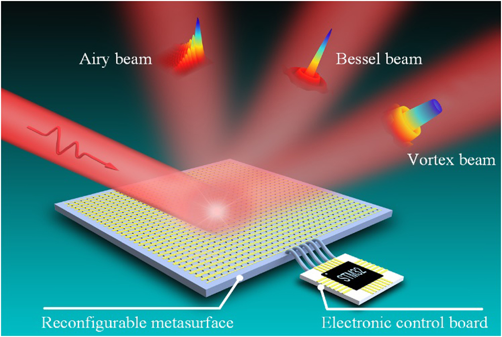
Figure 1.Schematic of complex beams generation exploiting the versatile metasurface platform. Three complex beams, including zeroth-order Bessel beam, vortex beam, and Airy beam, are generated by judiciously implementing the predefined phase profiles.
A schematic view of the elementary tunable meta-atom is shown in Figs. 2(a) and 2(b). The meta-atom is composed of three metal layers separated by two dielectric substrates ( and ) with thickness and . When an electric field is oriented perpendicularly to the two metal strips composing the top layer, a capacitive response is obtained. A MACOM MAVR-011020-1411 varactor diode with a dynamic capacitance range of 0.02 to 0.22 pF is loaded between the two strips and by applying a reversed DC bias voltage to the electronic element, total capacitance of the meta-atom can be precisely addressed. The second layer is a quasi-continuous reflective layer that brings an inductive response such that the meta-atom acts as an LC resonator whose frequency response can be properly addressed. To individually control each unit cell, the continuous strip of the capacitive layer is connected to the ground of the DC voltage supply, while the isolated strip is connected to its corresponding bias line located under the ground plane through a metal via, as shown in the Fig. 2(a). The equivalent circuit of the proposed meta-atom is depicted in the inset of Fig. 2(a). It is worth noting that the dimensions of the meta-atom have been optimized such that the intrinsic capacitance of the meta-atom can be neglected compared with the capacitance of the varactor diode. As such, the only capacitance that influences the resonance frequency of the RLC circuit is the one from the varactor diode.
![]()
Figure 2.Schematic design of the addressable meta-atom incorporating a voltage-biased varactor diode. (a) 3D view. The inset shows the equivalent circuit of the meta-atom. (b) Exploded perspective view. The geometrical parameters are
Though a single metal via is required to bias the varactor diode in each meta-atom, 15 vias are integrated in the top dielectric substrate, where 14 of them are blind vias and a single one is connected to the voltage supply through the lower substrate layer, as highlighted in Fig. 2(b). As the location of each meta-atom is different on the metasurface, the location of the through via connected to the power supply to bias the varactor diode also changes. It is worthwhile to note that integration of the numerous blind vias in each meta-atom is absolutely necessary since the location of the through via connected to the power supply has an influence on the EM response of the latter meta-atom. By using blind vias in the top dielectric substrate, the influence of the location of the via on the EM response is then suppressed and allows for a negligible phase change when the position of the meta-atom changes on the metasurface. Therefore, the geometry above the quasi-continuous ground plane is fixed no matter the position of the meta-atom on the metasurface. In each meta-atom, 15 metal feed lines printed on the bottom face of the lower substrate are connected to the positive DC voltage, where only a single one is connected to the through via.
In order to investigate the performance of the electronically addressable meta-atom, both simulations and measurements are carried out in the frequency band ranging from 7 to 11 GHz. The numerical simulations are accomplished with the commercial software HFSS from ANSYS based on the finite element method (FEM). A Floquet port is used as a plane wave source, illuminating the unit cell and periodic boundaries set along both and directions. The reflection coefficient of the meta-atom is depicted in Figs. 2(c)–2(f). Eight capacitance values are selected for the simulations to show the characteristic of the element by adjusting the DC voltage applied on the varactor diode. Microwave measurements are performed on the fabricated prototype in an anechoic chamber using a network analyzer and two 2 to 18 GHz broadband horn antennas. The reflection measurements are done by placing the emitting and receiving horn antennas on the same side of the prototype and inclined at an angle of about 5° with respect to the normal on the prototype surface. Phase referencing and magnitude normalization are performed in reflection, by replacing the sample by a copper plate. Quasi-full phase coverage reaching nearly 340° is achieved between 8.5 and 9.5 GHz. Furthermore, as highlighted in Fig. 3, the reflection amplitude and phase responses show quasi-no variation with the position change of the through via, due to the use of blind vias in the meta-atom design.
![]()
Figure 3.Reflection response of the meta-atom versus the position variation
Based on the above designed meta-atom, we physically implement a dynamic metasurface platform composed of unit cells. Due to the unit cell having 15 feed lines, a slit orthogonal to the feed lines is fabricated in the middle of the feed line layer of the metasurface. The numerical model is simulated using the HFSS software, where the full reconfigurable metasurface composed of meta-atoms is constructed. A radiation box is assigned around the metasurface. Lumped RLC boundaries are assigned for the varactor diodes, and a plane wave is applied to illuminate the metasurface. Photographs of the fabricated metasurface are depicted in Fig. 4. A sample covering a usable surface of is fabricated using conventional printed circuit board (PCB) technology, and the varactor diodes are soldered on the metasurface using surface-mount component soldering technique. The bottom layer of the sample, shown in Fig. 4(b), comprises 20 flexible printed circuit (FPC) connectors that are utilized to connect the 900 meta-atoms to the power supply system.
![]()
Figure 4.Photographs of the dynamic metasurface. (a) Top face of the fabricated sample. Ultrathin absorbing sheets, represented by the gray material, are placed around the usable surface to eliminate parasitic reflections. (b) Bottom face of the sample containing the bias lines and flexible printed circuit (FPC) connectors. (c) Usable part of the metasurface whose size is
3. RESULTS AND DISCUSSION
A. Bessel Beam Generation
The Bessel beam, whose transverse intensity can be described by the Bessel functions of the first kind, is a nondiffracting beam. To generate the zeroth-order Bessel beam, the phase profile of an axicon lens is applied to satisfy the following equation [41]:
The phase profile described in Eq. (1) is implemented on the reconfigurable metasurface, which is illuminated by a plane wave with the electric field polarized along the direction. The tilt angle of the Bessel beam phase profile is fixed to 14° for a Bessel beam generation with a single beam in the far field. The corresponding phase profiles of a zeroth-order Bessel beam for at 8.5, 9, and 9.5 GHz are shown, respectively, in Figs. 5(a)–5(c). Near-field experimental measurements are carried out by using a broadband horn antenna placed at 150 cm away from the reconfigurable metasurface as a quasi-planar wave source. An EFS-105-12 all-dielectric fiber-optic active antenna [49] fixed on computer-controlled linear stages, which has a small dielectric head of dimensions and can operate over 2 to 12 GHz frequency band with high sensitivity, is used as the field-sensing probe for the information collection of the magnitude and phase of the electric field in the scanning plane. Both the horn antenna and probe are connected to the vector network analyzer. The numerical and experimental near-field results of the zeroth-order Bessel beam are depicted in Fig. 5 at three different frequencies. The normalized magnitude distribution in both and planes illustrates the nondiffracting property of the zeroth-order Bessel beam. To further characterize the performance of the generated Bessel beam, the normalized magnitude and phase distributions at in the plane are shown in the subfigures of each panel.
![]()
Figure 5.(a)–(c) Phase profiles for the zeroth-order Bessel beam generation at 8.5, 9, and 9.5 GHz. (d)–(k) Numerical and experimental results of the zeroth-order Bessel beam at 8.5, 9, and 9.5 GHz. (d)–(f) Simulated electric field magnitude distributions in
Meanwhile, far-field simulations and measurements are also carried out to validate the performances. For the far-field measurements, the setup consists of using a small horn antenna in the 8.2–12.4 GHz frequency operation 50 cm far from the metasurface as feeding source. The feeding horn and the metasurface are placed on a rotating plate, and a broadband horn antenna is placed at 6 m away at the receiving end to collect the electric-field data in the far-field zone. A single beam is observed at the boresight (0°) in the and planes. It is clear that the Bessel beam is generated in a frequency band ranging from 8.5 to 9.5 GHz, which reveals the broadband property of the reconfigurable metasurface.
B. Vortex Beam Generation
As a method to enhance the channel capacity of communication links, orbital angular momentum (OAM) carried by vortex beams has attracted a lot of attention owing to the additional spatial degree of freedom and to the perfect orthogonality between different states, which is considered a promising transmission technique. To generate vortex beams, the phase shift to be implemented on the metasurface is expressed as [6]
The simulated near-field results utilizing the phase profile depicted in Fig. 6(a) for mode in the and planes are shown in Fig. 6(d) for 9.5 GHz frequency, where the hollow structure with null intensity at the center can be observed. The ring-shaped magnitude and spiral phase distributions, intrinsic features of OAM beams, can be clearly observed in the plane at . For the sake of demonstration, near-field measurements are also performed, where the doughnut-shaped structure and the vortex phase pattern can also be observed in Fig. 6(g), exhibiting a good agreement with the simulations. Besides, the hollow pattern can also be observed in the far-field region shown in Figs. 6(j) and 6(k), with a divergence angle of 30° between the two peaks.
![]()
Figure 6.(a)–(c) Phase profiles for the generation of different types of vortex beams carrying OAM mode
C. Focusing OAM
To convert the illuminating wave into a focusing vortex beam carrying OAM, a parabolic phase profile along the radial direction is superposed to the vortex beam phase profile for the focusing mechanism. Thus, the total phase for the focusing vortex beam satisfies the following equation [6]:
The near-field patterns of the focusing vortex beam using the phase profile shown in Fig. 6(b) are depicted in Figs. 6(e) and 6(h) with a focal length for an OAM mode at 9.5 GHz. The simulation and measurement results in the plane show that the energy of vortex beam converges at . It is worth noting that the beam decays rapidly along the propagation direction beyond the focal point. The ring-shaped magnitude at the focal plane clearly shows a smaller inner diameter than the original OAM vortex beam. In the far-field region beyond the focal point, the focusing OAM beam diverges more than in the original configuration, exhibiting a peak-to-peak divergence angle of around 40°. Besides, the main lobes of the focusing vortex beam in the far field show lower magnitude than those of the original vortex beam for both simulation and measurement, as illustrated in Figs. 6(j) and 6(k), confirming the decay feature. Such feature can be particularly interesting in near-field communications or energy harvesting where a high level of energy is desired at a well-defined spatial location.
D. Nondiffracting Vortex Beam
A higher-order Bessel beam can be interpreted as a zeroth-order Bessel beam carrying an orbital angular momentum. By superposing the original vortex beam that is inherently divergent and a zeroth-order Bessel beam, a nondiffracting vortex beam, which has a concentrated energy distribution along the propagating direction, is achieved. The phase profile of the nondiffracting vortex beam can then be written as [6]
The nondiffracting vortex beam is particularly interesting, as it provides a solution to the divergence drawback of vortex beams. For this purpose, the nondiffracting vortex beam with OAM mode and presenting the phase profile shown in Fig. 6(c) is implemented on the metasurface. The results are shown in Figs. 6(f) and 6(i). In such a configuration, it can be observed that the Bessel vortex beam is less divergent compared with the original one. Furthermore, a hollow beam with nondiffractive propagation is achieved over a propagation distance up to . Energy is concentrated around the central axis along the propagating direction in the plane. Besides, the far-field results in the plane highlight clearly the divergence reduction with the two main lobes at and the propagation characteristic enhancement with a higher energy of the main beam compared with the original vortex beam. Such a method of phase profile superposition can be further exploited to generate nondiffracting vortex beams with other topological modes.
E. Airy Beam Generation
An Airy beam, whose main beam propagates along a curved parabolic trajectory, is another kind of nondiffracting beam. The form of the Airy wave packet is verified as a solution to the Schrödinger equation describing a free particle [50]. Due to its diffraction-free characteristics, the Airy beam carries infinite energy, which in an experimental way is quasi-impossible to demonstrate. To overcome this problem and generate the Airy beam in an experimental environment, an exponential decaying factor is introduced to ensure a containment of the infinite Airy tail, and, despite such adjustment, the truncated Airy beam still exhibits a nondiffracting characteristic [51]. A one-dimensional Airy beam has been achieved from static and reconfigurable metasurfaces using the different possible schemes of phase only or amplitude and phase simultaneously modulation [52–54]. However, a 2D Airy beam has only been generated from static metasurfaces [55]. Here, we propose to generate a 2D Airy beam from the reconfigurable metasurface. The 2D Airy beam can be implemented by the product of two 1D Airy beams accelerating along the and directions, respectively [56]. Therefore, the electric field envelope of the 2D Airy beam is written as [56]
Figure 7 presents the results obtained for the implementation of a 2D Airy beam with parameters and by applying the phase profile presented in Fig. 7(a), which is calculated from Eq. (6). The simulated magnitude distributions are presented in Figs. 7(b)–7(d), where the 3D view of the Airy beam is represented by two transverse planes and one longitudinal plane located at the diagonal of the plane. The main Airy beam propagates along a parabolic trajectory in the longitudinal plane, as shown in Fig. 7(b). Owing to the equal transverse scale in the and directions, the total acceleration of the 2D Airy beam takes place along the diagonal direction of the plane. Besides, the acceleration along the and axes can also be observed for both transverse planes located at and , as shown in Figs. 7(c) and 7(d), where the highest energy spot is located in the upper right corner. The corresponding experimental measurements validate the characteristics of the 2D Airy beam, and the parabolic trajectory is clearly visible in Fig. 7(e).
![]()
Figure 7.(a) Phase profile for the generation of the 2D Airy beam with parameters
In addition to the above three complex beams, a plethora of other phase profiles, including beam splitting and hologram, can be considered and demonstrated from the elaborately designed dynamic metasurface. In a general manner, the proposed electronically reconfigurable metasurface can serve as a multitask platform to realize any functionality that can be implemented with a phase modulation. Besides, this reconfigurable metasurface is easy to integrate, which paves the way to construct software-controlled and intelligent meta-devices for the next generation of communication systems [57].
As a key factor to quantitatively evaluate the performances of the proposed metasurface platform for the different functionalities, the total efficiency is defined as the ratio of power carried by the complex beam with respect to the power of the incident wave :
The efficiency is extracted from the experimental data in the plane. In the case of the Bessel beam, the efficiency is found to be 34.47%, 34.32%, and 34.88% at 8.5, 9, and 9.5 GHz, respectively. For the generated mode 1 OAM beams at 9.5 GHz, the efficiency is calculated as 42.35% for the classical OAM beam at , 42.53% for the nondiffracting OAM beam at , and 38.66% for the focusing OAM beam at . Finally, the efficiency at of the generated Airy beam is calculated as 24.86%. Compared with passive multifunctional metasurfaces in Refs. [15,16] showing an efficiency higher than 72%, reconfigurable metasurfaces exhibit a lower efficiency [45–48], due to ohmic losses introduced by the electronic components. The performances obtained with the proposed metasurface are consistent with previous works, as summarized in Table 1. Comparison of Previous Studies on Multifunctional MetasurfacesRef. Frequency Band (GHz) Experimental Efficiency Type Electric Components Phase Coverage Individually Addressed T. Cai 10.22–11.15 91% Transmission/Reflection – 360° – T. Cai 8.4–11.2 90% Reflection – 360° – 9.1–11.7 72% Transmission – 360° – J. Y. Dai 2.7–3.7 – Reflection Varactor 270° No C. Qian 6.7–9.2 – Reflection Varactor 360° No K. Chen 6.7–7.1 36% Transmission Varactor No Z. Wang 5.5–6.0 20.7% Reflection Varactor No This work 8.5–9.5 24.8%–42.5% Reflection Varactor Yes
The absorption can then be calculated as
4. CONCLUSIONS
In summary, we have presented a novel 2D reflective reconfigurable metasurface, whose varactor diode-loaded meta-atom can be individually controlled by an elaborately designed voltage bias system to deliver a continuous phase variation, which can achieve an approximately phase coverage over a wide frequency band and have nearly the same phase response with the position change of through via by utilizing the blind technique. The proposed reconfigurable metasurface has been numerically verified and experimentally demonstrated for complex beams generation in a wide frequency band spanning from 8.5 to 9.5 GHz. Zeroth-order Bessel beams with axicon phase profiles and different types of vortex beams, including classical, focusing, and nondiffracting vortex beams, are generated. Furthermore, the 2D Airy beam is achieved utilizing the 1 bit binary phase coding method. Experimental measurements, in excellent agreement with numerical simulations, highlight the outstanding performance of the reconfigurable metasurface for wavefronts tailoring. It is worth noting that the dynamic metasurface can achieve other functionalities by appropriately implementing their corresponding phase profiles. Interestingly, such a phase-tuning programmable metasurface can serve as a versatile platform in the microwave regime for far- and near-field wavefront manipulations.
Acknowledgment
Acknowledgment. R. Feng is supported in part by the Doctoral Students’ Long-Term Study Abroad Scholarship Fund of Xidian University and by the Chinese Scholarship Council.
References
[1] B. Ratni, A. de Lustrac, G.-P. Piau, S. N. Burokur. Electronic control of linear-to-circular polarization conversion using a reconfigurable metasurface. Appl. Phys. Lett., 111, 214101(2017).
[2] J. Xu, R. Li, J. Qin, S. Wang, T. Han. Ultra-broadband wide-angle linear polarization converter based on H-shaped metasurface. Opt. Express, 26, 20913-20919(2018).
[3] X. Huang, H. Yang, D. Zhang, Y. Luo. Ultrathin dual-band metasurface polarization converter. IEEE Trans. Antennas Propag., 67, 4636-4641(2019).
[4] Y. Qi, B. Zhang, C. Liu, X. Deng. Ultra-broadband polarization conversion meta-surface and its application in polarization converter and RCS reduction. IEEE Access, 8, 116675-116684(2020).
[5] Q. Dai, Z. Li, L. Deng, N. Zhou, J. Deng, J. Tao, G. Zheng. Single-size nanostructured metasurface for dual-channel vortex beam generation. Opt. Lett., 45, 3773-3776(2020).
[6] K. Zhang, Y. Yuan, D. Zhang, X. Ding, B. Ratni, S. N. Burokur, M. Lu, K. Tang, Q. Wu. Phase-engineered metalenses to generate converging and non-diffractive vortex beam carrying orbital angular momentum in microwave region. Opt. Express, 26, 1351-1360(2018).
[7] B. Ratni, A. de Lustrac, G.-P. Piau, S. N. Burokur. Reconfigurable meta-mirror for wavefronts control: applications to microwave antennas. Opt. Express, 26, 2613-2624(2018).
[8] X. Fu, Y. Fan, J. Wang, Y. Li, M. Feng, H. Chen, W. Wang, J. Zhang, S. Qu. Ultra-wideband microwave absorber via an integrated metasurface and impedance-matching lattice design. J. Phys. D, 52, 31LT01(2019).
[9] Y. Kato, S. Morita, H. Shiomi, A. Sanada. Ultrathin perfect absorbers for normal incident waves using Dirac cone metasurfaces with critical external coupling. IEEE Microw. Wireless Compon. Lett., 30, 383-386(2020).
[10] Y. Li, A. Li, T. Cui, D. F. Sievenpiper. Multiwavelength multiplexing hologram designed using impedance metasurfaces. IEEE Trans. Antennas Propag., 66, 6408-6413(2018).
[11] Z. Wang, X. Ding, K. Zhang, B. Ratni, S. N. Burokur, X. Gu, Q. Wu. Huygens metasurface holograms with the modulation of focal energy distribution. Adv. Opt. Mater., 6, 1800121(2018).
[12] H. Ren, X. Fang, J. Jang, J. Bürger, J. Rho, S. A. Maier. Complex-amplitude metasurface-based orbital angular momentum holography in momentum space. Nat. Nanotechnol., 15, 948-955(2020).
[13] C. Guan, J. Liu, X. Ding, Z. Wang, K. Zhang, H. Li, M. Jin, S. N. Burokur, Q. Wu. Dual-polarized multiplexed meta-holograms utilizing coding metasurface. Nanophotonics, 9, 3605-3613(2020).
[14] L. Zhang, R. Y. Wu, G. D. Bai, H. T. Wu, Q. Ma, X. Q. Chen, T. J. Cui. Transmission-reflection integrated multifunctional coding metasurface for full-space controls of electromagnetic waves. Adv. Funct. Mater., 28, 1802205(2018).
[15] T. Cai, G. M. Wang, S. W. Tang, H. X. Xu, J. W. Duan, H. J. Guo, F. X. Guan, S. L. Sun, Q. He, L. Zhou. High-efficiency and full-space manipulation of electromagnetic wave fronts with metasurfaces. Phys. Rev. Appl., 8, 034033(2017).
[16] T. Cai, S. W. Tang, G. M. Wang, H. X. Xu, S. L. Sun, Q. He, L. Zhou. High-performance bifunctional metasurfaces in transmission and reflection geometries. Adv. Opt. Mater., 5, 1600506(2016).
[17] Y. Yuan, K. Zhang, B. Ratni, Q. Song, X. Ding, Q. Wu, S. N. Burokur, P. Genevet. Independent phase modulation for quadruplex polarization channels enabled by chirality-assisted geometric-phase metasurfaces. Nat. Commun., 11, 4186(2020).
[18] Y. Yuan, S. Sun, Y. Chen, K. Zhang, X. Ding, B. Ratni, Q. Wu, S. N. Burokur, C.-W. Qiu. A fully phase-modulated metasurface as an energy-controllable circular polarization router. Adv. Sci., 7, 2001437(2020).
[19] M. Rahmani, L. Xu, A. E. Miroshnichenko, A. Komar, R. Camacho-Morales, H. Chen, Y. Zárate, S. Kruk, G. Zhang, D. N. Neshev, Y. S. Kivshar. Reversible thermal tuning of all-dielectric metasurfaces. Adv. Funct. Mater., 27, 1700580(2017).
[20] X. Liu, Q. Wang, X. Zhang, H. Li, Q. Xu, Y. Xu, X. Chen, S. Li, M. Liu, Z. Tian, C. Zhang, C. Zou, J. Han, W. Zhang. Thermally dependent dynamic meta-holography using a vanadium dioxide integrated metasurface. Adv. Opt. Mater., 7, 1900175(2019).
[21] K. Z. Kamali, L. Xu, J. Ward, K. Wang, G. Li, A. E. Miroshnichenko, D. Neshev, M. Rahmani. Reversible image contrast manipulation with thermally tunable dielectric metasurfaces. Small, 15, 1805142(2019).
[22] M. R. Shcherbakov, S. Liu, V. V. Zubyuk, A. Vaskin, P. P. Vabishchevich, G. Keeler, T. Pertsch, T. V. Dolgova, I. Staude, I. Brener. Ultrafast all-optical tuning of direct-gap semiconductor metasurfaces. Nat. Commun., 8, 17(2017).
[23] X. G. Zhang, W. X. Tang, W. X. Jiang, G. D. Bai, J. Tang, L. Bai, C.-W. Qiu, T. J. Cui. Digital metasurfaces: light-controllable digital coding metasurfaces. Adv. Sci., 5, 1801028(2018).
[24] Y. Zhou, X. Y. Hu, C. Li, H. Yang, Q. H. Gong. All-optical tunable dual Fano resonance in nonlinear metamaterials in optical communication range. J. Mod. Opt., 65, 1-7(2018).
[25] J. Valente, J. Y. Ou, E. Plum, I. J. Youngs, N. I. Zheludev. A magneto-electro-optical effect in a plasmonic nanowire material. Nat. Commun., 6, 7021(2015).
[26] S. M. Kamali, E. Arbabi, A. Arbabi, Y. Horie, A. Faraon. Highly tunable elastic dielectric metasurface lenses. Laser Photon. Rev., 10, 1002-1008(2016).
[27] B. Gupta, S. Pandey, A. Nahata, T. Zhang, A. Nahata. Bistable physical geometries for terahertz plasmonic structures using shape memory alloys. Adv. Opt. Mater., 5, 1601008(2017).
[28] H. S. Ee, R. Agarwal. Tunable metasurface and flat optical zoom lens on a stretchable substrate. Nano Lett., 16, 2818-2823(2016).
[29] T. Roy, S. Zhang, I. W. Jung, M. Troccoli, F. Capasso, D. Lopez. Dynamic metasurface lens based on MEMS technology. APL Photon., 3, 021302(2018).
[30] E. Arbabi, A. Arbabi, S. M. Kamali, Y. Horie, M. Faraji-Dana, A. Faraon. MEMS-tunable dielectric metasurface lens. Nat. Commun., 9, 812(2018).
[31] Y. W. Huang, H. W. Lee, R. Sokhoyan, R. A. Pala, K. Thyagarajan, S. Han, D. P. Tsai, H. A. Atwater. Gate-tunable conducting oxide metasurfaces. Nano Lett., 16, 5319-5325(2016).
[32] J. Hwang, J. W. Roh. Electrically tunable two-dimensional metasurfaces at near-infrared wavelengths. Opt. Express, 25, 25071-25078(2017).
[33] Y. Li, J. Lin, H. Guo, W. Sun, S. Xiao, L. Zhou. A tunable metasurface with switchable functionalities: from perfect transparency to perfect absorption. Adv. Opt. Mater., 8, 1901548(2020).
[34] Y. Chai, H. Deng, Q. Xiong. A dynamically phase tunable metasurface for a broad bandwidth ultra-low radar cross section. IEEE Access, 8, 53006-53017(2020).
[35] A. de Lustrac, B. Ratni, G.-P. Piau, Y. Duval, S. N. Burokur. Tri-state metasurface-based electromagnetic screen with switchable reflection, transmission, and absorption functionalities. ACS Appl. Electron. Mater., 3, 1184-1190(2021).
[36] X. Bai, F. Kong, Y. Sun, G. Wang, J. Qian, X. Li, A. Cao, C. He, X. Liang, R. Jin, W. Zhu. High-efficiency transmissive programmable metasurface for multimode OAM generation. Adv. Opt. Mater., 8, 2000570(2020).
[37] X. Wan, M. Q. Qi, T. Y. Chen, T. J. Cui. Field-programmable beam reconfiguring based on digitally controlled coding metasurface. Sci. Rep., 6, 20663(2016).
[38] T. J. Cui, M. Q. Qi, X. Wan, J. Zhao, Q. Cheng. Coding metamaterials, digital metamaterials and programming metamaterials. Light Sci. Appl., 3, e218(2014).
[39] H. Yang, X. Cao, F. Yang, J. Gao, S. Xu, M. Li, X. Chen, Y. Zhao, Y. Zheng, S. Li. A programmable metasurface with dynamic polarization, scattering and focusing control. Sci. Rep., 6, 35692(2016).
[40] C. Huang, C. Zhang, J. Yang, B. Sun, B. Zhao, X. Luo. Reconfigurable metasurface for multifunctional control of electromagnetic waves. Adv. Opt. Mater., 5, 1700485(2017).
[41] R. Feng, B. Ratni, J. Yi, Z. Jiang, H. Zhang, A. de Lustrac, S. N. Burokur. Flexible manipulation of Bessel-like beams with a reconfigurable metasurface. Adv. Opt. Mater., 8, 2001084(2020).
[42] H.-X. Xu, S. Tang, S. Ma, W. Luo, T. Cai, S. Sun, Q. He, L. Zhou. Tunable microwave metasurfaces for high-performance operations: dispersion compensation and dynamical switch. Sci. Rep., 6, 38255(2016).
[43] V. Popov, B. Ratni, S. N. Burokur, F. Boust. Non-local reconfigurable sparse metasurface: efficient near-field and far-field wavefront manipulations. Adv. Opt. Mater., 9, 202001316(2021).
[44] B. Liu, Y. He, S.-W. Wong, Y. Li. Multifunctional vortex beam generation by a dynamic reflective metasurface. Adv. Opt. Mater., 9, 2001689(2020).
[45] J. Y. Dai, J. Zhao, Q. Cheng, T. J. Cui. Independent control of harmonic amplitudes and phases via a time-domain digital coding metasurface. Light Sci. Appl., 7, 90(2018).
[46] C. Qian, B. Zheng, Y. Shen, L. Jing, E. Li, L. Shen, H. Chen. Deep-learning-enabled self-adaptive microwave cloak without human intervention. Nat. Photonics, 14, 383-390(2020).
[47] K. Chen, Y. Feng, F. Monticone, J. Zhao, B. Zhu, T. Jiang, L. Zhang, Y. Kim, X. Ding, S. Zhang, A. Alù, C.-W. Qiu. A reconfigurable active Huygens’ metalens. Adv. Mater., 29, 1606422(2017).
[48] Z. Wang, D. Liao, T. Zhang, T. Chen, Y. Ruan, B. Zheng. Metasurface-based focus-tunable mirror. Opt. Express, 27, 30332-30339(2019).
[49] http://www.enprobe.de/products_FO-Antennas.htm. http://www.enprobe.de/products_FO-Antennas.htm
[50] M. V. Berry, N. L. Balazs. Nonspreading wave packets. Am. J. Phys., 47, 264-267(1979).
[51] R. Feng, B. Ratni, J. Yi, K. Zhang, X. Ding, H. Zhang, A. de Lustrac, S. N. Burokur. Versatile Airy-beam generation using a 1-bit coding programmable reflective metasurface. Phys. Rev. Appl., 14, 014081(2020).
[52] E. Song, G. Lee, H. Park, K. Lee, J. Kim, J. Hong, H. Kim, B. Lee. Compact generation of Airy beams with C-aperture metasurface. Adv. Opt. Mater., 5, 1601028(2017).
[53] H. Li, W. Hao, X. Yin, S. Chen, L. Chen. Broadband generation of Airy beams with hyperbolic metamaterials. Adv. Opt. Mater., 7, 1900493(2019).
[54] Q. Fan, D. Wang, P. Huo, Z. Zhang, Y. Liang, T. Xu. Autofocusing Airy beams generated by all-dielectric metasurface for visible light. Opt. Express, 25, 9285-9294(2017).
[55] Z.-W. Miao, Z.-C. Hao, B.-B. Jin, Z. N. Chen. Low-profile 2-D THz Airy beam generator using the phase-only reflective metasurface. IEEE Trans. Antennas Propag., 68, 1503-1513(2019).
[56] Y. Huang, J. Li, H.-X. Xu, H. Yu, Z. Yang, P. Yu, W. Hu, D. Inserra, G. Wen. Experimental demonstration of microwave two-dimensional Airy beam generation based on single-layer metasurface. IEEE Trans. Antennas Propag., 68, 7507-7516(2020).
[57] C. Liaskos, S. Nie, A. Tsioliaridou, A. Pitsillides, S. Ioannidis, I. Akyildiz. A new wireless communication paradigm through software-controlled metasurfaces. IEEE Commun. Mag., 56, 162-169(2018).

Set citation alerts for the article
Please enter your email address
© Copyright 2018-2021 | Chinese Laser Press. All Rights Reserved 沪ICP备15018463号-20