
Avihai Aharon (Akram), Daniel Rozban, Avi Klein, Amir Abramovich, Yitzhak Yitzhaky, Natan S. Kopeika. Detection and upconversion of three-dimensional MMW/THz images to the visible[J]. Photonics Research, 2016, 4(6): 306
- Photonics Research
- Vol. 4, Issue 6, 306 (2016)
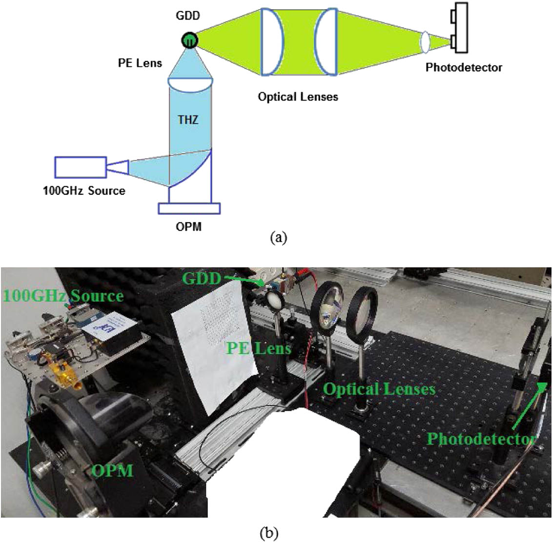
Fig. 1. Experimental setup of the upconversion detection: (a) schematic, (b) picture.
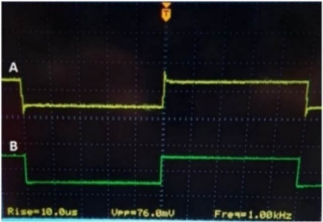
Fig. 2. Detected signal from the photodetector (signal A, 76 mV peak to peak) and modulation signal of the MMW/THz radiation (signal B) on the same time axis.
Fig. 3. Detected signal from the photodetector (solid line) and the detected signal from the electronic circuit without amplifier (dashed line) as a function of the GDD DC bias current.
Fig. 4. Detected signal from the photodetector (signal A) and modulation signal of the MMW/THz radiation (signal B). The response time of the detection using the PDB210A photodetector was found to be 480 ns.
Fig. 5. Setup configuration for the upconversion imaging system using a GDD and photodetector.
Fig. 6. Pictures of the setup configuration for the upconversion imaging system using a GDD and photodetector, imaging mirror, and metal object with a size of 8 cm × 10 cm
Fig. 7. Imaging results: (a) the raw upconverted MMW/THz image, (b) the image after thresholding low values.
Fig. 8. Setup configuration for an optical FMCW experiment at 100 GHz using a photodetector and GDD lamp N523 in side configuration, connected to the detection electronic circuit and external amplifier.
Fig. 9. Detected signal A and modulation signal B for the FMCW experiment: (a) upconversion optical heterodyne detection, (b) electronic heterodyne detection.
Fig. 10. FFT of the detected signal from the FMCW experiment: (a) upconversion optical heterodyne detection, (b) electronic heterodyne detection.

Set citation alerts for the article
Please enter your email address
© Copyright 2018-2021 | Chinese Laser Press. All Rights Reserved 沪ICP备15018463号-20