• Journal of Infrared and Millimeter Waves
  • Vol. 39, Issue 4, 422 (2020)
Duo XU1, Shao-Meng WANG2, Wei SHAO1, Teng-Long HE1, He-Xin WANG1, Tao TANG1, Hua-Rong GONG1, Zhi-Gang LU1, Zhan-Liang WANG1, Zhao-Yun DUAN1, Yan-Yu WEI1, Jin-Jun FENG3, and Yu-Bin GONG1、*
Author Affiliations
  • 1School of Electronic Science and Engineering, University of Electronic Science and Technology of China, Chengdu60054, China
  • 2Satellite Research Centre, Nanyang Technological University, Singapore639798
  • 3Beijing Vacuum Electronics Research Institute, Beijing100015, China
  • show less
    DOI: 10.11972/j.issn.1001-9014.2020.04.005 Cite this Article
    Duo XU, Shao-Meng WANG, Wei SHAO, Teng-Long HE, He-Xin WANG, Tao TANG, Hua-Rong GONG, Zhi-Gang LU, Zhan-Liang WANG, Zhao-Yun DUAN, Yan-Yu WEI, Jin-Jun FENG, Yu-Bin GONG. Investigation of low-voltage broadband overmoded folded rectangular coaxial waveguide TWT at W-band[J]. Journal of Infrared and Millimeter Waves, 2020, 39(4): 422 Copy Citation Text show less
    Sketches of (a) folded rectangular waveguide, and (b) FRCW-SWS
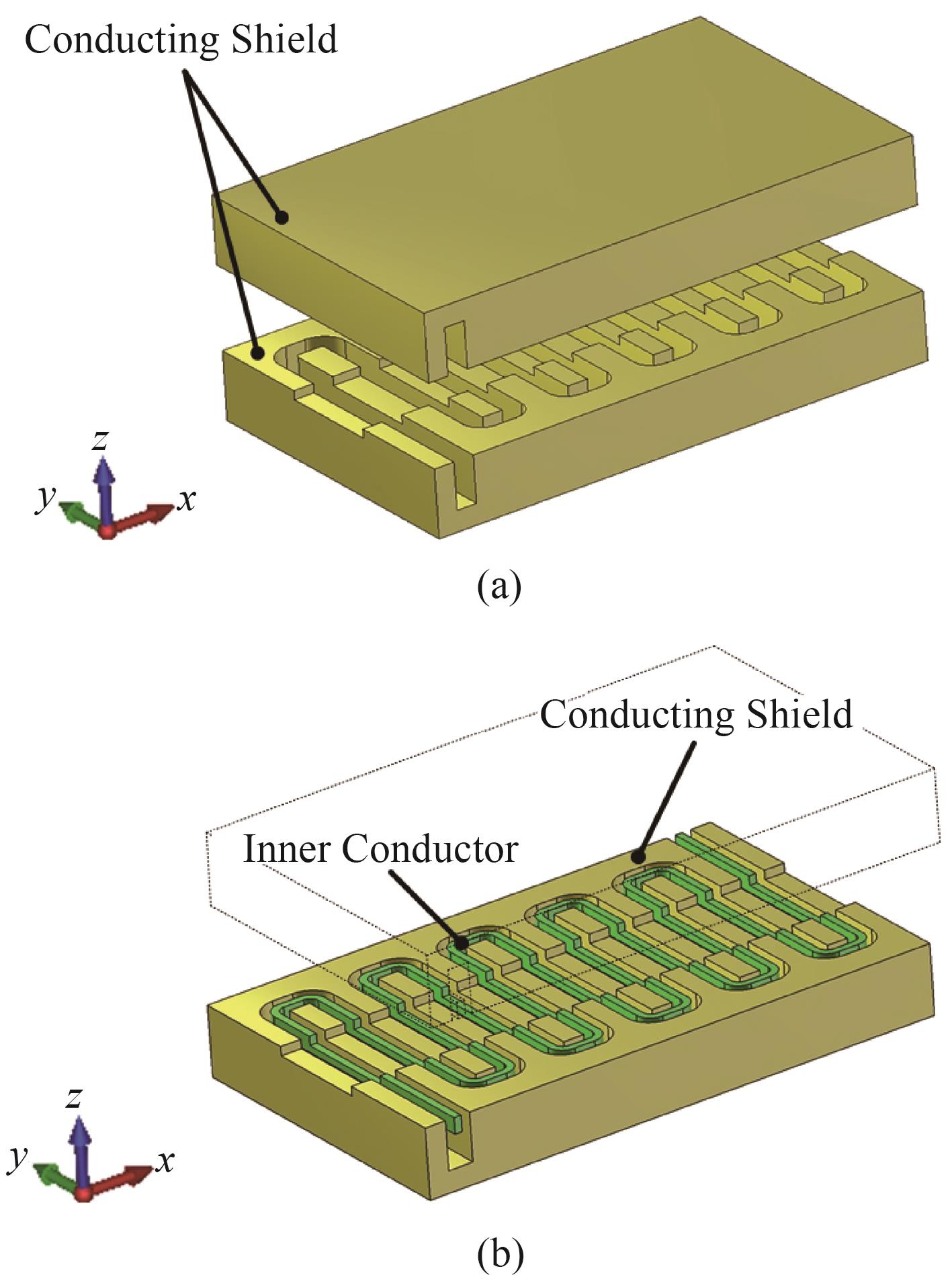
    Fig. 1. Sketches of (a) folded rectangular waveguide, and (b) FRCW-SWS
    (a) The model, and (b) the top view of the conducting shield and the dielectric poles in one period
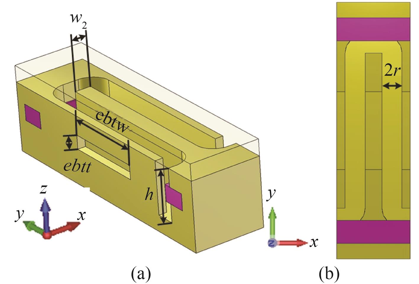
    Fig. 2. (a) The model, and (b) the top view of the conducting shield and the dielectric poles in one period
    (a) The model and (b) the top view of the inner conductor and the dielectric poles in one period
    Fig. 3. (a) The model and (b) the top view of the inner conductor and the dielectric poles in one period
    Scalar diagram and vector diagram of electric field intensity distribution of (a,c) the fundamental mode, and (b,d) the second order mode
    Fig. 4. Scalar diagram and vector diagram of electric field intensity distribution of (a,c) the fundamental mode, and (b,d) the second order mode
    (a) Dispersion curves of the FRCW-SWS, (b,c) The normalized phase velocities, and (d,e) the interaction impedances of wave in the FRCW-SWS in various w and t of the second order mode
    Fig. 5. (a) Dispersion curves of the FRCW-SWS, (b,c) The normalized phase velocities, and (d,e) the interaction impedances of wave in the FRCW-SWS in various w and t of the second order mode
    (a) The position of electron beam in the SWS, (b) the distribution of sampling points in the cross section of the electron beam, and (c) average pierce interaction impedance in the cross section of the electron beam
    Fig. 6. (a) The position of electron beam in the SWS, (b) the distribution of sampling points in the cross section of the electron beam, and (c) average pierce interaction impedance in the cross section of the electron beam
    (a) The model, (b) the front cross section view, and (c) the side cross section view of the rectangular coaxial waveguide to rectangular waveguide converter
    Fig. 7. (a) The model, (b) the front cross section view, and (c) the side cross section view of the rectangular coaxial waveguide to rectangular waveguide converter
    (a) Return loss, and (b) insertion loss of the converter
    Fig. 8. (a) Return loss, and (b) insertion loss of the converter
    The transmission characteristics of the FRCW slow wave system with the converters
    Fig. 9. The transmission characteristics of the FRCW slow wave system with the converters
    (a) The sketch and (b) the transmission characteristics of the truncated FRCW-SWS without the converters
    Fig. 10. (a) The sketch and (b) the transmission characteristics of the truncated FRCW-SWS without the converters
    The diagram of (a) ideal rectangular source face of electrons, (b) presupposed longitudinal uniform magnetic field
    Fig. 11. The diagram of (a) ideal rectangular source face of electrons, (b) presupposed longitudinal uniform magnetic field
    (a) The amplitudes of input and output, (b) the frequency spectrum of output signal, (c) the distribution of the kinetic energy of electrons along with different longitudinal position
    Fig. 12. (a) The amplitudes of input and output, (b) the frequency spectrum of output signal, (c) the distribution of the kinetic energy of electrons along with different longitudinal position
    Output power and gain of the FRCW-TWT with 45 mW sinusoidal signal as input signal
    Fig. 13. Output power and gain of the FRCW-TWT with 45 mW sinusoidal signal as input signal
    Symbollw2rwtPhebtwebttdpwdpt
    Value/mm20.070.10.070.30.540.6410.170.20.2
    Table 1. Dimensional parameters of the designed SWS
    Symbolabrdrwrlrhtrlcpcil
    Value/mm2.541.270.5450.35331.168150.8080.610
    Table 2. Dimensional parameters of the designed converter
    ParameterValue
    Beam Voltage3230 V
    Beam Current0.15 A
    Beam Cross Section0.9 mm × 0.07 mm
    Longitudinal Magnetic Field1T
    Input Power45 mW
    Table 3. Operating condition of the designed TWT
    Duo XU, Shao-Meng WANG, Wei SHAO, Teng-Long HE, He-Xin WANG, Tao TANG, Hua-Rong GONG, Zhi-Gang LU, Zhan-Liang WANG, Zhao-Yun DUAN, Yan-Yu WEI, Jin-Jun FENG, Yu-Bin GONG. Investigation of low-voltage broadband overmoded folded rectangular coaxial waveguide TWT at W-band[J]. Journal of Infrared and Millimeter Waves, 2020, 39(4): 422
    Download Citation