
Duo XU, Shao-Meng WANG, Wei SHAO, Teng-Long HE, He-Xin WANG, Tao TANG, Hua-Rong GONG, Zhi-Gang LU, Zhan-Liang WANG, Zhao-Yun DUAN, Yan-Yu WEI, Jin-Jun FENG, Yu-Bin GONG. Investigation of low-voltage broadband overmoded folded rectangular coaxial waveguide TWT at W-band[J]. Journal of Infrared and Millimeter Waves, 2020, 39(4): 422
- Journal of Infrared and Millimeter Waves
- Vol. 39, Issue 4, 422 (2020)
Abstract
Keywords
Introduction
Traveling wave tube is one type of high efficiency microwave amplifier with wide applications. Since invented at 1940s, it has been used in many microwave and electronic devices, such as radar and satellite communication systems, due to its characteristics of high power, high gain, broad operating band and so on. However, with the increase of operating frequency, the difficulty of processing of the SWS of traditional helix TWT raises rapidly. Thus, many novel SWSs have been proposed by researchers at millimeter wave and submillimeter wave band.
Folded rectangular waveguide (FRW) is a well-known SWS for millimeter wave and submillimeter wave TWTs. In general, FRW-TWT[
To develop a TWT with high operating frequency, broad bandwidth, and low operating voltage, a novel SWS named FRCW-SWS is proposed in this paper. The proposed novel SWS is set to work at the second order mode to increase the operating frequency and reduce the operating voltage.
Compared to FRW-SWS, the bandwidth of the proposed FRCW-SWS is much broader. Meanwhile, the proposed FRCW-SWS can work at higher frequency waveband than the conventional planar miniaturized SWSs.
The novel FRCW-SWS is formed by folding the rectangular coaxial waveguide along the axial direction. Waveguide input/output port is selected for the W-band FRCW-SWS TWT as it has a higher power capacity. To match the broad bandwidth of FRCW-SWS, a rectangular coaxial waveguide to standard rectangular waveguide converter is designed for the input/output structure.
This paper is organized as follows. Section II gives a detailed description of the novel SWS, explaining the structure and the main parameter. The operation mode and advantages of the novel FRCW-SWS is analyzed in Section III. In addition, Section III gives the high frequency characteristics of the novel SWS. Section IV presents the double-ridges loaded waveguide to rectangular coaxial waveguide converter for the input/output structure of the novel FRCW-SWS. Finally, Section V shows the setting and results of beam-wave interaction simulation.
1 Description of SWS
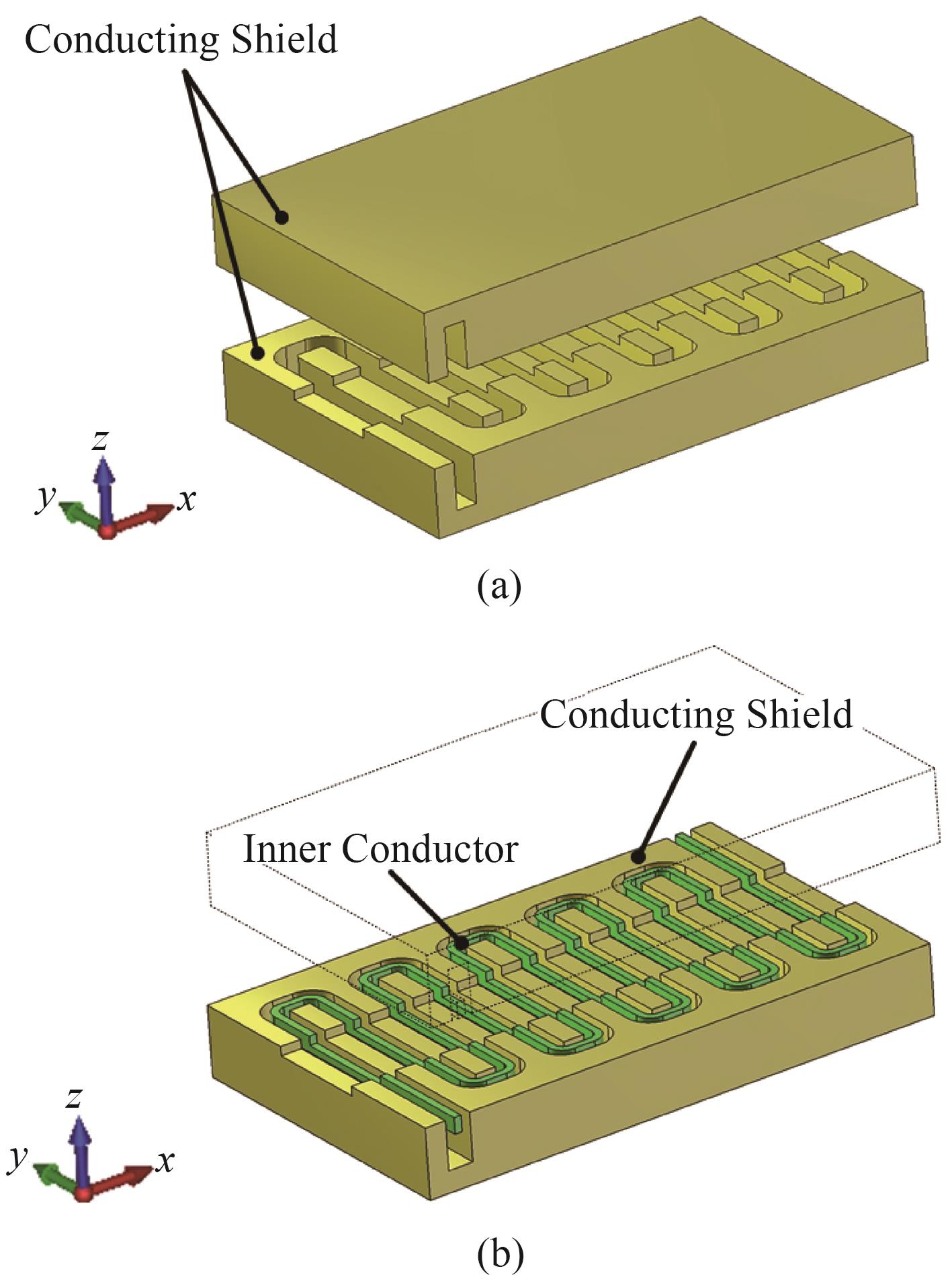
Coaxial waveguide is known as a type of transmission line containing an inner conductor and a conducting shield. As the electric field distribution in rectangular coaxial waveguide[
![]()
Figure 1.Sketches of (a) folded rectangular waveguide, and (b) FRCW-SWS
In consideration of the physical truth, two dielectric poles are placed in the conducting shield to hold the inner conductor. The dielectric poles are made of diamond, with a relative permittivity of 5.68. The FRCW-SWS is a periodic structure and a unit cell can nearly express all structure characteristics. Detailed sketches of one FRCW unit and the diagram of the meander route are shown in
![]()
Figure 2.(a) The model, and (b) the top view of the conducting shield and the dielectric poles in one period
![]()
Figure 3.(a) The model and (b) the top view of the inner conductor and the dielectric poles in one period
2 High frequency characteristics of FRCW-SWS
2.1 Analyses of operating mode
The FRCW-SWS has many advantages such as broad bandwidth, low operating voltage and high operating frequency. The reasons of these advantages are analyzed as follows.
First, the fundamental mode of the coaxial waveguide is TEM mode while the fundamental mode of the rectangular waveguide is TE10 mode. The dispersion characteristics of TEM mode are much weaker than that of TE10 mode. As a result, we can predict that the bandwidth of the FRCW-SWS is much broader than that of the FRW-SWS.
In addition, compared to other SWSs working at TEM or Quasi-TEM mode, such as microstrip meander line SWS and strip meander line SWS, the bandwidth of the novel FRCW-SWS is broader. That can be explained by the equivalent circuit[
The addition inductance caused by the coupling among the transverse sections of the inner conductor varies with frequency, which is the main cause of dispersion. The isolation of conducting shield from the transverse sections of the inner conductor reduces the coupling strength of the transverse sections, therefore, the additional inductance of the novel FRCW-SWS is smaller than that of the conventional microstrip meander line SWS or strip meander line. So, the bandwidth of the FRCW-SWS is broader.
The low voltage of the FRCW-SWS can be explained by two aspects. One is that the phase velocity of TEM mode is lower than that of TE10 mode.
The other one can be explained as follows. The proposed FRCW-SWS works at overmode state, specifically the second order mode, the corresponding frequency of which is higher. The second order mode is also TEM mode, the same as the fundamental mode, but its frequency is higher, and wavelength is shorter. The wavelength of the fundamental mode is over the length of the meander path in one period and but the wavelength of the second order mode is shorter than that and over half of that. The electric field distributions of fundamental mode and second order mode are shown in
![]()
Figure 4.Scalar diagram and vector diagram of electric field intensity distribution of (a,c) the fundamental mode, and (b,d) the second order mode
According to the relation between the propagation modes and the path length of one single period, in order to make the FRCW-SWS working at the fundamental mode, it requires that the length of meander path in a single period is shorter than the wavelength of the TEM wave propagating along the meander path. It means that when the SWS is working at the fundamental mode, the transverse width is limited to be shorter than a half of the wavelength. But while the SWS works at overmode state, the limit mentioned above could be broken. Thus, the transverse width and aspect ratio are approximately doubled without changing the length of period. These explained the low operating voltage characteristics of the novel FRCW-SWS.
2.2 Dispersion characteristics
The values of the marked parameters in Figs.
| Symbol | l | w2 | r | w | t | P | h | ebtw | ebtt | dpw | dpt |
|---|---|---|---|---|---|---|---|---|---|---|---|
| Value/mm | 2 | 0.07 | 0.1 | 0.07 | 0.3 | 0.54 | 0.64 | 1 | 0.17 | 0.2 | 0.2 |
Table 1. Dimensional parameters of the designed SWS
![]()
Figure 5.(a) Dispersion curves of the FRCW-SWS, (b,c) The normalized phase velocities, and (d,e) the interaction impedances of wave in the FRCW-SWS in various w and t of the second order mode
To acquire the dispersion characteristics of the FRCW-SWS with parameters listed in
2.3 Interaction impedance
The other significant high frequency characteristic of a SWS is Pierce interaction impedance[
![]()
Figure 6.(a) The position of electron beam in the SWS, (b) the distribution of sampling points in the cross section of the electron beam, and (c) average pierce interaction impedance in the cross section of the electron beam
3 Rectangular waveguides to coaxial waveguide converter
Rectangular waveguide to coaxial waveguide or coaxial waveguide to rectangular waveguide transition is a valuable question of microwave transmission field and has been investigated by many researchers. There are multifarious theories[
In order to cooperate the proposed broadband SWS, a broadband double-ridges loaded waveguide to rectangular coaxial waveguide converter is developed.
The converter contains two transitions in fact. One is rectangular coaxial waveguide to double-ridges loaded waveguide and the other one is double-ridges loaded waveguide to W-band standard rectangular waveguide (WR-10).
![]()
Figure 7.(a) The model, (b) the front cross section view, and (c) the side cross section view of the rectangular coaxial waveguide to rectangular waveguide converter
The optimized values of structure parameters are listed in
| Symbol | a | b | rd | rw | rl | rh | trl | cp | cil |
|---|---|---|---|---|---|---|---|---|---|
| Value/mm | 2.54 | 1.27 | 0.545 | 0.353 | 3 | 1.168 | 15 | 0.808 | 0.610 |
Table 2. Dimensional parameters of the designed converter
![]()
Figure 8.(a) Return loss, and (b) insertion loss of the converter
As can be seen, the designed converter has a prominent performance of broad band. At the frequency range of 74~113 GHz, the return loss of converter stands below -20dB and the insertion loss is less than -0.5 dB.
Then, a pair of the proposed converter are assembled with a section of 33-periods FRCW-SWS as the input/output structure, as shown in
![]()
Figure 9.The transmission characteristics of the FRCW slow wave system with the converters
In the simulation, all the metal parts are set as oxygen free copper. Considering the influence of surface roughness to the conductivity of metal at W-band, the copper conductivity is considered to be σ = 2.2×10⁷ S/m.
4 Beam-wave interaction simulation
To verify the hot performance of the designed SWS, the beam-wave interaction has been investigated using CST-Particle Studio. To reduce the simulation time and promote the accuracy of calculation, the converters were not included in the PIC simulation.
In the interest of avoiding band edge oscillation, the TWT is truncated into two segments. The numbers of periods are 24 and 33 in in part 1 and part 2, respectively. The overall length of this TWT in 32 mm. The PIC simulation model and its transmission characteristics are shown in
![]()
Figure 10.(a) The sketch and (b) the transmission characteristics of the truncated FRCW-SWS without the converters
It is worth noting that the Port 3 and Port 4 are reserved for connecting to coaxial attenuator to depress band edge oscillation. In the simulation, they are set as waveguide ports to extract redundant electromagnetic energy.
In order to explore the capability of the proposed SWS, an ideal sheet electron beam generated by a rectangular electron emitter and a presupposed longitudinal uniform focusing magnetic field are used instead of real electron beam and magnetic field in the simulation.
![]()
Figure 11.The diagram of (a) ideal rectangular source face of electrons, (b) presupposed longitudinal uniform magnetic field
The emission area is set to 0.9 mm × 0.07 mm and the intensity of the required presupposed longitudinal uniform magnetic field is about 1T. In this case, the presupposed magnetic field can restrict the electrons in electron beam tunnel effectively and no electron is observed hitting at the end side of the SWS.
The operating condition of the simulated TWT is enumerated in
| Parameter | Value |
|---|---|
| Beam Voltage | 3230 V |
| Beam Current | 0.15 A |
| Beam Cross Section | 0.9 mm × 0.07 mm |
| Longitudinal Magnetic Field | 1T |
| Input Power | 45 mW |
Table 3. Operating condition of the designed TWT
For acquiring the ability of TWT to amplify the power of electromagnetic wave, sinusoidal signal was used as input signal of TWT to drive it.
![]()
Figure 12.(a) The amplitudes of input and output, (b) the frequency spectrum of output signal, (c) the distribution of the kinetic energy of electrons along with different longitudinal position
![]()
Figure 13.Output power and gain of the FRCW-TWT with 45 mW sinusoidal signal as input signal
5 Conclusion
A novel SWS named FRCW-SWS was proposed in this paper. The high frequency characteristics were calculated by using HFSS. The simulation results showed that it has a much broader operating bandwidth than conventional FRW-SWSs and miniaturized planar SWSs.
In addition, a double-ridges loaded rectangular coaxial line to standard rectangular waveguide of W-band (WR-10) converter is presented and designed in this paper. The simulation results show that the designed converter can transform the mode of electromagnetic wave effectively.
In general, the operating bandwidths of the reported W-band FRW-TWTs are less than 15% and their operating voltage is about 20 kV. The PIC simulation results in CST indicate that the bandwidth of the novel TWT is 36.56% centered at 93GHz and the operating voltage is 3230 V. That illuminates that the novel overmode FRCW-TWT has clear advantages in the aspects of bandwidth and operating voltage than FRW-TWT. In addition, the maximal output power, gain and RF efficiency of the novel TWT are 27.4 W, 27.8 dB and 5.65% respectively.
References
[1] R K Sharma, A Grede, S Chaudhary. Design of folded waveguide slow-wave structure for W-Band TWT. IEEE Transactions on Plasma Science, 42, 3430-3436(2014).
[2] J J Feng, J Cai, Y F Hu. Development of W-band folded waveguide pulse TWTs. IEEE Transactions on Electron Devices, 60, 1721-1725(2014).
[3] Y Y Wei, G Guo, Y B Gong. Novel W-band ridge-loaded folded waveguide traveling wave tube. IEEE Electron Device Letters, 35, 1058-1060(2014).
[4] J Cai, J J Feng, Y F Hu. 10 GHz Bandwidth 100 Watt W-band folded waveguide pulsed TWTs. IEEE Microwave and Wireless Components Letters, 24, 620-621(2014).
[5] L W Liu, Y Y Wei, F Shen. A Novel Winding Microstrip meander-line slow wave structure for V-band TWT. IEEE Electron Device Letters, 34, 1325-1327(2013).
[6] C Chua, S Aditya. A 3-D U-shaped meander-line slow-wave structure for traveling-wave-tube applications. IEEE Transactions on Electron Devices, 60, 1251-1256(2013).
[7] C Chua, S Aditya, Z X Shen. Design of a planar helix with straight-edge connections for traveling-wave tube applications. India, 207-208(2011).
[8] N F Bai, L L Gu, C S Shen. S-shaped microstrip meander-line slow-wave structure for W-band traveling-wave tube. France, 1-2(2013).
[9] G Ulisse, V Krozer. Investigation of a planar metamaterial slow wave structure for traveling wave tube applications. UK, 1-2(2017).
[10] A I Benedik, N M Ryskin. Planar V-Band Slow-Wave Structures for Low-Voltage Tubes with Sheet Electron Beam. UK, 1-2(2017).
[11] S M Wang, Y B Gong, Y Hou. Study of a log-periodic slow wave structure for Ka-band radial sheet beam traveling wave tube. IEEE Transactions on Plasma Science, 41, 2277-2282(2013).
[12] H X Wang, Z L Wang, X Y Li. Study of a miniaturized dual-beam TWT with planar dielectric-rods-support uniform metallic meander line. physics of plasmas, 25(2018).
[13] Y H Cho, H J Eom. Fourier transform analysis of a ridge-waveguide and a rectangular coaxial line. Radio Science, 36, 533-538(2001).
[14] J H Booske, M C Converse, C L Kory. Accurate parametric modeling of folded waveguide circuits for millimeter-wave traveling wave tubes. IEEE Transactions on Electron Devices, 52, 685-694(2005).
[15] M Sumathy, K J Vinoy, S K Datta. Analysis of ridge-loaded folded-waveguide slow-wave structures for broadband traveling-wave tubes. IEEE Transactions on Electron Devices, 57, 1440-1446(2010).
[16] Y Hou, Y B Gong, J Xu. A novel ridge-vane-loaded folded-waveguide slow-wave structure for 0.22 THz traveling-wave tube. IEEE Transactions on Electron Devices, 60, 1228-1235(2013).
[17] J R Pyle. The cutoff wavelength of the TE10 mode in ridged rectangular waveguide of any aspect ratio. IEEE Transactions on Microwave Theory and Techniques, 14, 175-183(1966).
[18] D M Pozar. Microwave engineering. NY(2004).
[20] A G Williamson. Analysis and modeling of a coaxial-line/rectangular-waveguide junction. Optics and Antennas, 129, 271-277(1982).
[21] S M Saad. A more accurate analysis and design of coaxial-to-rectangular waveguide and launcher. IEEE Transactions on Microwave Theory and Techniques, 38, 129-134(1990).
[22] R B Keam. Broadband design of coaxial line/rectangular waveguide probe transition. Antennas and Propagation, 141, 53-58(1994).
[23] V A Rudakov, V A Sledkov, A P Mayorov. Compact wide-band coaxial-to waveguide microwave transactions for X and Ku bands. Ukraine, 522-523(2013).

Set citation alerts for the article
Please enter your email address
© Copyright 2018-2021 | Chinese Laser Press. All Rights Reserved 沪ICP备15018463号-20