Abstract
Near-infrared excited rare-earth (RE)-doped up-conversion (UC)-luminescent materials have attracted enormous attention because of their unique emission properties, such as narrow emission bands, long luminescence lifetimes, and multiple colors. However, current development of RE-doped luminescent material is hindered by weak and narrowband absorption problems and low photon-conversion quantum efficiencies. In addition to conventional approaches to enhance fluorescence intensity, controlling emission directivity to improve detection efficiency has become a promising approach to obtain higher luminescence brightnesses. In this paper, a self-suspended RE-doped UC luminescent waveguide is designed to realize directional emissions. Benefitting from the special morphology of the crown-like NaYF4:Yb3+/Er3+ microparticle, the points contact between the waveguide and substrate can be obtained to decrease energy loss. An attractive UC luminescent pattern accompanied by powerful and controllable directional emissions is observed, and the spatial emission angle and intensity distribution are explored and analyzed in detail by introducing Fourier imaging detection and simulation. This work provides a new method for achieving controllable directional fluorescence emissions and obtaining improved detection efficiency by narrowing emission directivity, which has potential applications in 3-dimensional displays and micro-optoelectronic devices, especially when fabricating self-fluorescence micron lasers.Introduction
Compared with organic dyes and quantum dots, which realize photon up-conversion (UC) via molecular triplet-triplet annihilation or second-harmonic generation, near-infrared excited rare-earth (RE)-doped UC luminescent materials are ideal candidates for nonlinear UC via multiphoton absorption processes because of their massive anti-Stokes shift, narrow emission bandwidth, superior photostability, and low phototoxicity1-4. The current development of RE-doped luminescent materials has suffered from low luminescence brightnesses, owing to their relatively weak and narrowband absorptions and low photon-conversion quantum efficiencies, which have significantly limited their applications to energy harvesting, bioimaging, labelling, optical storage, and photo switching5-9. Enhancing the fluorescence intensity or narrowing the emission directivity are both essential goals toward achieving full control of fluorescence and obtaining improved detection efficiencies10, 11. Over the past decades, increasing attention has been paid to investigating UC mechanisms and designing new and more complex structures to obtain high UC efficiency5, 12-14. However, investigation on the control of emission directivity of UC luminescence has been extremely lacking.
Luminescent waveguides are effective for guiding the transmission of light while controlling the radiation direction on the micro/nano scale15-20. Recently, micro/nano materials with various regular morphologies have been widely obtained, giving us an opportunity to investigate lanthanide-doped UC-luminescent waveguides under the total reflection theory21-23. However, for conventional shaped waveguides (e.g., hexagonal discs or tubes), the energy loss is caused by an excessive contact area with the substrate, which significantly limits transition, and emission efficiency24-26. The general solution has been to apply protective coatings at positions where the sample contacts the substrate or to introduce a coating layer having a proper refractive index at the surface27, 28. However, these approaches are complicated, and can create an additional channel for energy loss with scattering at the interface.
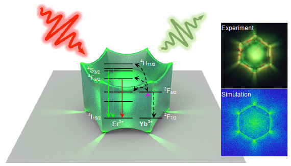
In this work, a self-suspended UC-luminescent waveguide is realized using a RE-doped crown-shaped microparticle. Benefitting from the points of contact, an air layer is formed between the waveguide and substrate, greatly reducing the energy-coupling loss and enhancing transmission and emission efficiency. As shown in Fig. 1, under the excitation of a 980-nm laser, an attractive UC-luminescent pattern, accompanied by a controllable directional emission, is calculated and observed experimentally. Transmission and emission modes are explored in detail using Fourier imaging. This new scheme provides a method that can achieve controllable directional emission, providing potential applications to self- luminescent micron lasers.

Figure 1.Schematic of the directional UC emission of crown-shaped NaYF4:Yb3+/Er3+ under an excitation of 980 nm and the experimental and simulated UC luminescent patterns.
Results and discussion
NaYF4:Yb3+/Er3+ crown-like hexagonal microparticles were synthesized using a sodium-citrate assistant hydrothermal method. The SEM images of the particles are shown in Figs. 2(a) and 2(b). As shown, the as-synthesized crown-shaped NaYF4:Yb3+/Er3+ microcrystals having a diameter of ~6 μm and a thickness of ~3 μm are uniformly distributed. The energy dispersive X-ray spectroscopy of a single microparticle (Fig. 2(c)) demonstrated uniform distribution of elements. The hexagonal phase and high crystallinity of the product were also confirmed via X-ray diffraction (XRD), as shown in Fig. 2(d). A beautiful flower-like UC emission revealing obvious directional radiation was observed under an excitation of 980 nm, as shown in Fig. 3(a). Corresponding UC emission spectra are shown in Fig. 3(b), where it can be seen that the UC emissions are centered at green (540 & 520 nm) and red (654 nm) wavebands (Fig. 3(c)). The incident photon of 980 nm laser is firstly captured by the Yb3+ ions accompanied the population of 2F5/2 level. And the energy is efficiently transferred to the Er3+ ions, and the 4I15/2 level is pumped to the excited level of 4I11/2. Part of electrons located at the 4I11/2 level will jump to the 4F7/2 excited level via the second energy transfer from Yb3+ ((2F5/2) - (2F7/2)) to Er3+ ((4I11/2) - (4F7/2)) ions, as described in Fig. 3(c). After that, most of the electrons from the 4F7/2 excited level will decay to the 2H11/2 and then to 4S3/2 levels by the non-radiative transition process. Finally, the green emissions (2H11/2 - 4I15/2 and 4S3/2 - 4I15/2) and red emission (4F9/2 - 4I15/2) are observed. For the red emission, two available channels are involved in populating the 4F9/2 level. Firstly, the 4S3/2 level can directly decay to the 4F9/2 level via the non-radiative transition. On the other hand, the electrons populated at the 4I11/2 level can also nonradiatively decay to the 4I13/2 level. Subsequently, the energy transfer from the Yb3+ to Er3+ ion occurs, leading to the population of the 4F9/2 level. Ultimately, the intense red emission is generated29, 30. However, for an ordinary disk waveguide, it is hard to realize the directional radiation (Fig. S1), and the detected luminescence intensity is obviously lower than the crown-shape waveguide (Fig. S2).
Figure 2.(a–b) SEM images of NaYF4:Yb3+/Er3+ microparticles, the cross-section of single microparticle shown in the inset image in (b). (c) Element mapping of a single NaYF4:Yb3+/Er3+ microparticle. (d) XRD pattern of the particles and standard pattern of the hexagonal phases of NaYF4.
Figure 3.(a–b) UC fluorescence patterns and spectra obtained through change excitation position from the center to corner/edge. (c) Energy-level diagram and possible transitions/emission schemes of Yb3+ and Er3+.
To investigate the directional radiation and waveguide mode of the self-suspended microparticle, a confocal microscopy system was used to collect the fluorescence of NaYF4:Yb3+/Er3+. It was found that, when the excitation positions were tuned, the directions of the waveguide emission were totally different, as shown in Fig. 3(a). A beautiful flower-like UC emission image having obvious directional radiation was observed, and the fluorescence uniformly emitted from the six corners of the particle when the laser focused on the center of the microparticle. While, if the excitation position of 980 nm laser was moved from the center to one edge of the UC luminescent particle, it showed inhomogeneous radiation along the six corners, and the corner direction emission deflected to the opposite direction of the laser-focused side (Fig. 3(a)). This phenomenon also appeared, when the laser focus was transferred to the corner of the hexagonal microcrystal. Furthermore, the UC emission intensity slightly reduced when the focal point was moved from the center to the corner and edge of the hexagonal particle, because more photons were used to excite the lanthanide ions from their ground states to excited states when the laser focused on the middle of the particle. However, when the focal point was tuned to the edge/corner of the waveguide, more photons were wasted because of the additional scattering and reflecting. Apart from the edge and corner excitation, the difference of fluorescence propagating modes under center and off-center excitation was also investigated (Figs. 4(a-j)). As shown in Figs. 4(a) and 4(f), when the excitation position was slightly off-centered, the corresponding pattern also showed a small deviation. Under the two excitation conditions, the patterns of the green and red emission bands were obtained. For the two-emission bands, there was no obvious change in the patterns under both center and off-center excitation because of the relatively shorter propagation path (Figs. 4(b-c) and 4(g-h)).
The attractive luminescence patterns under different laser-focused positions could be attributed to the relatively special geometry of the waveguide. When the 980 nm laser was excited on a single NaYF4:Yb3+/Er3+ microcrystal with the transitions of doped Er3+, Yb3+ ions, visible photons were emitted, propagating into the microcavity produced by the luminescent particle (nmicroparticle = 1.43, nair = 1). According to Snell's law, the total reflection angle was 44.4°31. After reflection and refraction, the fluorescence radiated from the microparticle finally resulted in special patterns. This assumption was supported via simulation using the geometrical optical theory. As shown in Figs. 4(d) and 4(i), the simulated results agree well with the experimental results shown in Figs. 4(a) and 4(f). The possible propagated paths of light in the microcavity are shown in Figs. 4(e) and 4(j). As the excited lanthanide ions perform as the luminescence center, the position of the laser focus determined the fluorescence transmission modes. When the position of excitation laser was set to the center of the waveguide, some luminescent ions were excited, and a kind of cylindrical fluorescent light source was formed in the microparticle. With the fluorescence emission of ions, some photons propagated upward, reflecting through the top surface and the side surface, finally emitting from the particles (Fig. 4(e)). During this process, the light was deflected to the diagonal direction, according of Fresnel's law, and was focused by the projection of gallery, finally leading to the strongest emission near the corner. The emitted photons that propagated downward focused and formed a circular region, shown in the middle of the UC emission patterns. Therefore, under center excitation, the optical image displayed a strong corner emission (Fig. 4(d)). With off-center excitation, the luminescence experienced diverse reflection and refraction (Fig. 4(j)), finally producing an asymmetrical corner emission that shows a reverse migration to the laser focus (Fig. 4(i)).
Figure 4.(a–e) UC luminescence patterns of total (a), green (b), and red (c) emissions, the simulation pattern (d), and possible propagation/emission mode (e) of single NaYF4:Yb3+/Er3+ under excited conditions on the middle. (f–j) UC luminescence patterns of total (f), green (g), and red (h) emissions, the simulation pattern (i), and possible propagation/emission modes (j) of single NaYF4:Yb3+/Er3+ under off-centered excitation.
In order to understand the directional emission of the luminescent waveguide, Fourier imaging was carried to precisely analyze the space angle of the UC fluorescence emission. The fluorescence emission was collected with an air objective having a numerical aperture (NA) of 0.9. The optical patterns on the image plane and the angular intensity distribution of radiation on the Fourier plane were obtained, as shown in Fig. 5. The angles (θ, φ) are shown by polar coordinates, in which φ= 100° indicates that the radiation is parallel to the diagonal of the radiation corner, and θ= 0° indicates that the radiation is parallel to the horizontal plane. Here, the value of θ was limited by the NA of objective and could be pressed as nairsinθ ≤ NA. Therefore, it is clear that θ is less than or equal to 64°. The collected areas of the back-focus plane (BFP) image of the microparticle were selected using an aperture slot placed on the image plane19. The observed optical image is shown in Figs. 5(a, e, i), and the left corner of the particle was chosen as the collection area, marked with a white circle. The excitation position was tuned, marked with red circle. The orange circle in the BFP images represents the maximal θ value (64°) (Figs. 5(b, f, j)).
Figure 5.The directional emission of the luminescent waveguide with center (a–d) and off-center excitations (upward offset, e–h, and downward offset, i–l).(a, e, i) optical pattern on the image plane, in which the excitation and collection positions were marked with red and white circles, (b, f, g) experimental and (c, g, k) simulated Fourier images of the selected region, and (d, h, i) the angular intensity distribution of radiation on the Fourier plane taken along the direction, where θ has maximum intensity. The insert images show the φ distributions on the Fourier plane.
According to geometrical optical theory, the radiation mode of a luminescent waveguide can be adjusted by tuning the position of the light source. In the experiment, the laser focus position was precisely controlled. When excited at the center of the microparticle, the intensity distribution was arc shaped and showed maximal intensity when the radiation was parallel to the diagonal (φ = 100°), and the θ distribution range was 46°-64° (Figs. 5(a-d)). Given the off-center excitation, the intensity distribution showed an clockwise arc rotation, the θ range decreased to 50°-58° at φ = 100°, and the maximum radiation intensity moved to the direction of φ = 72° (Figs. 5(e-h)). This indicates that the main radiation of fluorescence deviated from the diagonal direction. When the focus position of the off-center excitation was offset in the opposite direction, angle θ also decreased at φ = 100°, and the maximum radiation intensity moved to φ = 123° (Figs. 5(i-l)). The changed emission angle indicates that the transform of fluorescence propagated in the waveguide, which is consistent with the previous analysis. The Fourier images and angular spatial patterns were simulated. As shown in Figs. 5(c, g, k), the spatially oriented corner radiation mode and the emission angle having a different excited fluorescent center presented similar trends to the experimental results. To further study the radiation mode polarization dependences, a 980 nm polarizing film was inserted to the light path, and the results are shown in Fig. S3. For different polarizations, the Fourier images remained almost unchanged. Thus, the polarization of excitation laser had no effect on the geometrical optical properties of the luminescent waveguide.
Conclusion
A crown-like NaYF4:Yb3+/Er3+ microcrystal used as a luminescent waveguide was synthesized using the hydrothermal method to investigate the UC-luminescent propagation and directional emission. The unusual UC luminescent pattern was observed to be accompanied by powerful and controllable corner radiation, and the spatial emission angle and intensity distribution were analyzed in detail using Fourier imaging methods. Furthermore, the phenomenon in the experiment was consistent with the simulation results executed with the geometrical optical theory, and it was shown that the fluorescence total reflection mode was suited to the self-suspended UC luminescent waveguide. Moreover, combined analysis of the Fourier imaging and simulation was useful to exploring the transmission and emission modes of the RE-doped nano/micro UC-luminescent waveguide. This work provides a new method for achieving a directional controlled fluorescence emission and obtained improved detection efficiency by narrowing the emission directivity. It should offer potential applications for 3D display and micro-optoelectronic devices, especially when fabricating self-fluorescence micron lasers.
Method
Er(NO3)3·5H2O (99.9%), Yb(NO3)3·5H2O (99.9%), Y(NO3)3·6H2O (99.9%), were purchased from Shanghai Aladdin Biochemical Technology Co., Ltd. Analytical-grade sodium fluoride (NaF, 98.00%) and sodium citrate (Na3C6H5O7·2H2O, 99.00%) were purchased from Sinopharm Chemical Reagent Co., Ltd. (China). The special morphological NaYF4: Yb3+/Tm3+ microcrystals were synthesized via a modified hydrothermal method32. First, 0.3 mmol (0.2 mol/L) aqueous solution of RE(NO3)3 (RE = Y, Yb, Tm) was added to 21 ml deionized water with 0.5 mmol sodium citrate in a 100 ml beaker, and the mixture was stirred for 30 min. Then, 6.0 ml NaF (1 mol/L) aqueous solution was added to the beaker, and the resultant solution was stirred for about 25 min. Finally, the suspension was transferred into a Teflon-lined autoclave, heated to 200 ℃ and kept for 24 h. The resulting sample was separated via centrifugation, finally washed with deionized water and ethanol, and dried under 60 ℃ for several hours.
The surface morphology was obtained via scanning electron microscope (SEM) imaging (FEI-Nova NanoSEM 450) operating at a voltage of 10 kV. UC-luminescence spectra were collected by a spectrometer (SP2750i, 0.008 nm) equipped with a PIXIS 100 charge-coupled device (CCD, ACTON) and a PD471 photomultiplier tube (PMT, ACTON). The excitation source was the Ti sapphire femtosecond laser (Mira-900). The laser was focused through an air objective (NA = 0.9, 100×) on the sample, and the optical signal was collected by the same objective for luminescence imaging and Fourier imaging. The powder XRD pattern was measured using a Rigaku D/Max2550VB+/PC diffractometer. The luminescence photographs were observed via upright Olympus BX51 confocal microscopy with a Canon 75 600D. The excitation positions were tuned by moving the electric translation stage, and the patterns of the green and red emission bands were obtained with a 550-nm low-pass filter/600-nm high-pass filter placed on the front side of the CCD. The laser-focus position was precisely controlled by a piezoelectric ceramic translation stage. All measurements were conducted at room temperature. Simulation was analyzed in a ZEMAX non-sequence mode.
Acknowledgements
This work was supported by the National Natural Science Foundation of China (Grant Nos. 11574190 and 11504224), the National Science Foundation of Shaanxi Province (Grant Nos. 2019JQ-142 and 2019JM-441), and the Fundamental Research Funds for Central Universities (Grant Nos. GK201701008, 201903013, and 2017TS013).
Competing interests
The authors declare no competing financial interests.
Supplementary information
References
[1] Y M Wu, J H Xu, E T Poh, L L Liang, H L Liu et al. Upconversion superburst with sub-2 μs lifetime. Nat Nanotechnol, 14, 1110-1115(2019).
[2] X H Zhu, J Zhang, J L Liu, Y Zhang. Recent progress of rare- earth doped upconversion nanoparticles: synthesis, optimization, and applications. Adv Sci, 6, 1901358(2019).
[3] E M Chan. Combinatorial approaches for developing upconverting nanomaterials: high-throughput screening, modeling, and applications. Chem Soc Rev, 44, 1653-1679(2015).
[4] W Xu, X Chen, H W Song. Upconversion manipulation by local electromagnetic field. Nano Today, 17, 54-78(2017).
[5] B Zhou, B Y Shi, D Y Jin, X G Liu. Controlling upconversion nanocrystals for emerging applications. Nat Nanotechnol, 10, 924-936(2015).
[6] F Wang, X G Liu. Recent advances in the chemistry of lanthanide-doped upconversion nanocrystals. Chem Soc Rev, 38, 976-989(2009).
[7] Y Y Gu, Z Y Guo, W Yuan, M Y Kong, Y L Liu et al. High-sensitivity imaging of time-domain near-infrared light transducer. Nat Photonics, 13, 525-531(2019).
[8] S Y Han, R R Deng, X J Xie, X G Liu. Enhancing luminescence in lanthanide-doped upconversion nanoparticles. Angew Chem Int Ed Engl, 53, 11702-11715(2014).
[9] G K Liu. Advances in the theoretical understanding of photon upconversion in rare-earth activated nanophosphors. Chem Soc Rev, 44, 1635-1652(2015).
[10] J B Zhao, D Y Jin, E P Schartner, Y Q Lu, Y Q Liu et al. Single-nanocrystal sensitivity achieved by enhanced upconversion luminescence. Nat Nanotechnol, 8, 729-734(2013).
[11] H Aouani, O Mahboub, N Bonod, E Devaux, E Popov et al. Bright unidirectional fluorescence emission of molecules in a nanoaperture with plasmonic corrugations. Nano Lett, 11, 637-644(2011).
[12] Y Q Hu, Q Y Shao, Y Dong, J Q Jiang. Energy loss mechanism of upconversion core/shell nanocrystals. J Phys Chem C, 123, 22674-22679(2019).
[13] F Wang, Y Han, C S Lim, Y H Lu, J Wang et al. Simultaneous phase and size control of upconversion nanocrystals through lanthanide doping. Nature, 463, 1061-1065(2010).
[14] C C Mao, K Min, K Bae, S Cho, T Xu et al. Enhanced upconversion luminescence by two-dimensional photonic crystal structure. ACS Photonics, 6, 1882-1888(2019).
[15] G Bulgarini, M E Reimer, M Bouwes Bavinck, K D Jöns, D Dalacu et al. Nanowire waveguides launching single photons in a Gaussian mode for ideal fiber coupling. Nano Lett, 14, 4102-4106(2014).
[16] Z P Li, F Hao, Y Z Huang, Y R Fang, P Nordlander et al. Directional light emission from propagating surface plasmons of silver nanowires. Nano Lett, 9, 4383-4386(2009).
[17] T Shegai, S Chen, V D Miljković, G Zengin, P Johansson et al. A bimetallic nanoantenna for directional colour routing. Nat Commun, 2, 481(2011).
[18] Z Y Fang, L R Fan, C F Lin, D Zhang, A J Meixner et al. Plasmonic coupling of bow tie antennas with Ag nanowire. Nano Lett, 11, 1676-1680(2011).
[19] Z X Wang, H Wei, D Pan, H X Xu. Controlling the radiation direction of propagating surface plasmons on silver nanowires. Laser Photonics Rev, 8, 596-601(2014).
[20] M Mongillo, P Spathis, G Katsaros, P Gentile, S De Franceschi. Multifunctional devices and logic gates with undoped silicon nanowires. Nano Lett, 12, 3074-3079(2012).
[21] S Z Huang, H Chen, T He, C J Zhang, C Y Zhang et al. High-performance upconversion luminescent waveguide using a rare-earth doped microtube with beveled ends. J Mater Chem C, 7, 12704-12708(2019).
[22] Q Y Han, C Y Zhang, C Wang, Z J Wang, C X Li et al. Unique adjustable UC luminescence pattern and directional radiation of peculiar-shaped NaYF4: Yb3+/Er3+ microcrystal particle. Sci Rep, 7, 5371(2017).
[23] J Haas, E V Catalan, P Piron, M Karlsson, B Mizaikoff. Infrared spectroscopy based on broadly tunable quantum cascade lasers and polycrystalline diamond waveguides. Analyst, 143, 5112-5119(2018).
[24] C Bing, T Y Sun, X S Qiao, X P Fan, F Wang. Directional light emission in a single NaYF4 microcrystal via photon upconversion. Adv Opt Mater, 3, 1577-1581(2015).
[25] W Xu, T K Lee, B S Moon, D L Zhou, H W Song et al. Spectral and spatial characterization of upconversion luminescent nanocrystals as nanowaveguides. Nanoscale, 9, 9238-9245(2017).
[26] M G Debije, P P C Verbunt, B C Rowan, B S Richards, T L Optics. Measured surface loss from luminescent solar concentrator waveguides. Appl Opt, 47, 6763-6768(2008).
[27] L Luan, P R Sievert, W Mu, Z Hong, J B Ketterson. Highly directional fluorescence emission from dye molecules embedded in a dielectric layer adjacent to a silver film. New J Phys, 10, 073012(2008).
[28] D X Dai, Z Wang, J F Bauters, M C Tien, M J R Heck et al. Low-loss Si3N4 arrayed-waveguide grating (de)multiplexer using nano-core optical waveguides. Opt Express, 19, 14130-14136(2011).
[29] B Dong, R N Hua, B S Cao, Z P Li, Y Y He et al. Size dependence of the upconverted luminescence of NaYF4:Er, Yb microspheres for use in ratiometric thermometry. Phys Chem Chem Phys, 16, 20009-20012(2014).
[30] P Du, A M Deng, L H Luo, J S Yu. Simultaneous phase and size manipulation in NaYF4:Er3+/Yb3+ upconverting nanoparticles for a non-invasion optical thermometer. New J Chem, 41, 13855-13861(2017).
[31] V I Sokolov, A V Zvyagin, S M Igumnov, S I Molchanova, M M Nazarov et al. Determination of the refractive index of β-NaYF4/Yb3+/Er3+/Tm3+ nanocrystals using spectroscopic refractometry. Opt Spectrosc, 118, 609-613(2015).
[32] Q Y Han, W Gao, C Y Zhang, X H Mi, X Zhao et al. Tunable flower-like upconversion emission and directional red radiation in a single NaYF4:Yb3+/Tm3+ microcrystal particle. J Alloy Compd, 748, 252-257(2018).