• Opto-Electronic Advances
  • Vol. 3, Issue 3, 190022-1 (2020)
Lei Zhang1、*, Jing Pan1, Zhang Zhang1, Hao Wu1, Ni Yao1, Dawei Cai1, Yingxin Xu1, Jin Zhang1, Guofei Sun2, Liqiang Wang1, Weidong Geng2, Wenguang Jin3, Wei Fang1, Dawei Di1、4, and Limin Tong1
Author Affiliations
  • 1State Key Laboratory of Modern Optical Instrumentation, College of Optical Science and Engineering, Zhejiang University, Hangzhou 310027, China
  • 2College of Computer Science and Technology, Zhejiang University, Hangzhou 310027, China
  • 3College of Information Science and Electronic Engineering, Zhejiang University, Hangzhou 310027, China
  • 4Cavendish Laboratory, University of Cambridge, JJ Thomson Avenue, Cambridge CB3 0HE, United Kingdom
  • show less
    DOI: 10.29026/oea.2020.190022 Cite this Article
    Lei Zhang, Jing Pan, Zhang Zhang, Hao Wu, Ni Yao, Dawei Cai, Yingxin Xu, Jin Zhang, Guofei Sun, Liqiang Wang, Weidong Geng, Wenguang Jin, Wei Fang, Dawei Di, Limin Tong. Ultrasensitive skin-like wearable optical sensors based on glass micro/nanofibers[J]. Opto-Electronic Advances, 2020, 3(3): 190022-1 Copy Citation Text show less
    Fabrication and characterization of MNF-embedded PDMS patches.(a) SEM image of a 900-nm-diameter glass MNF with a bending radius of 30 μm. Inset: close-up image of the MNF showing smooth surface and uniform diameter. (b) Optical microscope image of a 1-μm-diameter glass MNF spiral guiding a 633-nm optical signal on a MgF2 substrate. (c) Photograph of a bent MNF-embedded PDMS patch. (d) Photograph of a MNF-embedded PDMS patch attached on human hand. (e) Optical microscope images of three patches with straight (left), bent (middle), and wavy (right) MNFs, respectively. (f) Optical microscope images of two MNFs guiding 532-and 633-nm signals separately. The two MNFs are assembled into side-by-side (top) and perpendicular crossing structures (bottom), with no crosstalk observed.
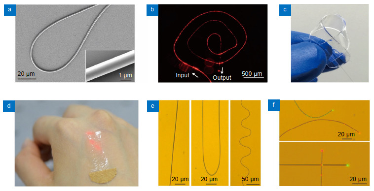
    Fig. 1. Fabrication and characterization of MNF-embedded PDMS patches.(a) SEM image of a 900-nm-diameter glass MNF with a bending radius of 30 μm. Inset: close-up image of the MNF showing smooth surface and uniform diameter. (b) Optical microscope image of a 1-μm-diameter glass MNF spiral guiding a 633-nm optical signal on a MgF2 substrate. (c) Photograph of a bent MNF-embedded PDMS patch. (d) Photograph of a MNF-embedded PDMS patch attached on human hand. (e) Optical microscope images of three patches with straight (left), bent (middle), and wavy (right) MNFs, respectively. (f) Optical microscope images of two MNFs guiding 532-and 633-nm signals separately. The two MNFs are assembled into side-by-side (top) and perpendicular crossing structures (bottom), with no crosstalk observed.
    Characterization of substrate supported SLWOSs.(a) Schematic of testing a SLWOS on a glass slide. (b) Optical field intensity distributions of 900-nm-wavelength light guiding along a 1-µm-diameter glass MNF embedded in a 5°-bent SLWOS. (c) Photograph of light leaking out of a SLWOS upon a finger touch. (d) Lateral pressure response of a SLWOS with MNF diameters of 0.8, 1.5 and 2.8 µm, respectively. (e) Pressure response of a SLWOS with a wide spectral range. (f) Typical response of a SLWOS to finger movements of tapping, non-contact movement and dragging successively. (g) Long-term operational characteristics of a SLWOS measured by alternately applying/removing a 2-kPa pressure for more than 10, 000 cycles.
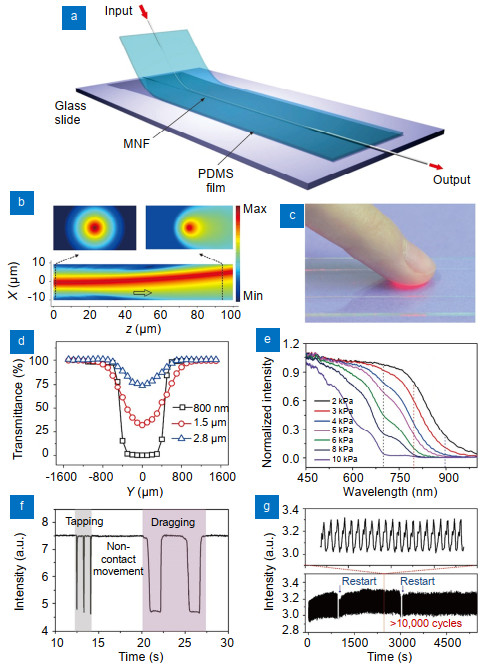
    Fig. 2. Characterization of substrate supported SLWOSs.(a) Schematic of testing a SLWOS on a glass slide. (b) Optical field intensity distributions of 900-nm-wavelength light guiding along a 1-µm-diameter glass MNF embedded in a 5°-bent SLWOS. (c) Photograph of light leaking out of a SLWOS upon a finger touch. (d) Lateral pressure response of a SLWOS with MNF diameters of 0.8, 1.5 and 2.8 µm, respectively. (e) Pressure response of a SLWOS with a wide spectral range. (f) Typical response of a SLWOS to finger movements of tapping, non-contact movement and dragging successively. (g) Long-term operational characteristics of a SLWOS measured by alternately applying/removing a 2-kPa pressure for more than 10, 000 cycles.
    Characterization of suspended SLWOSs.(a) Schematic of testing suspended SLWOS. (b) Response of a suspended SLWOS to water droplets with different weights. The inset shows an optical micrograph of the SLWOS with a water droplet atop. (c) Response of a suspended SLWOS to pressure of 2.1, 1.3, 0.2 and 0.1 Pa, respectively. (d) Temporary response of a suspended SLWOS to forced oscillation frequencies of 1, 4 and 20 kHz, respectively. (e) Response of a suspended SLWOS to acoustic vibrations from human voice. (f) Photograph showing a SLWOS directly above the artery of the wrist. The inset shows a schematic of the SLWOS. (g) Measurement of wrist pulse under normal-condition (66 beats per minute).
    Fig. 3. Characterization of suspended SLWOSs.(a) Schematic of testing suspended SLWOS. (b) Response of a suspended SLWOS to water droplets with different weights. The inset shows an optical micrograph of the SLWOS with a water droplet atop. (c) Response of a suspended SLWOS to pressure of 2.1, 1.3, 0.2 and 0.1 Pa, respectively. (d) Temporary response of a suspended SLWOS to forced oscillation frequencies of 1, 4 and 20 kHz, respectively. (e) Response of a suspended SLWOS to acoustic vibrations from human voice. (f) Photograph showing a SLWOS directly above the artery of the wrist. The inset shows a schematic of the SLWOS. (g) Measurement of wrist pulse under normal-condition (66 beats per minute).
    Optical data gloves and SLWOS with perpendicularly intersected 2×2 MNF arrays.(a) Photograph showing a five-sensor data glove integrated with 5 SLWOSs. (b) Bending-angle-dependent output of a typical SLWOS. (c) Close-up view of the SLWOS output within bending angles of 60.0°–60.8°. (d) Photograph showing a SLWOS consisted by a perpendicularly intersected 2×2 MNF array. (e) Schematic of the sensing areas for tactile sensing. (f) Logic outputs of a 4-input/output-port SLWOS.
    Fig. 4. Optical data gloves and SLWOS with perpendicularly intersected 2×2 MNF arrays.(a) Photograph showing a five-sensor data glove integrated with 5 SLWOSs. (b) Bending-angle-dependent output of a typical SLWOS. (c) Close-up view of the SLWOS output within bending angles of 60.0°–60.8°. (d) Photograph showing a SLWOS consisted by a perpendicularly intersected 2×2 MNF array. (e) Schematic of the sensing areas for tactile sensing. (f) Logic outputs of a 4-input/output-port SLWOS.
    Lei Zhang, Jing Pan, Zhang Zhang, Hao Wu, Ni Yao, Dawei Cai, Yingxin Xu, Jin Zhang, Guofei Sun, Liqiang Wang, Weidong Geng, Wenguang Jin, Wei Fang, Dawei Di, Limin Tong. Ultrasensitive skin-like wearable optical sensors based on glass micro/nanofibers[J]. Opto-Electronic Advances, 2020, 3(3): 190022-1
    Download Citation