Optical geometrical transformation is a novel and powerful tool to switch orbital angular momentum (OAM) states in modern optics. We demonstrate a scheme to operate multiplication and division in OAM by Fermat’s spiral transformation. The characteristics of the output beams in the case of integer and fraction OAM operations are presented in detail. Additionally, the power weight of the output OAM modes and the interference patterns of the output beams are reported to confirm the expected ability of OAM mode conversion by Fermat’s spiral transformation. We further investigate the evolution of OAM beams in operations theoretically and experimentally. This work provides a practical way to perform an optical transformation mapping on OAM beams. It can find application in optical communications with larger OAM mode numbers as well as quantum information in high-dimensional systems.
1. INTRODUCTION
Light beams with a spiral phase wavefront and an annular intensity profile carry orbital angular momentum (OAM). OAM of per photon is a natural property of the beams comprising a spiral phase structure , where is the topological charge, is the azimuthal angle, and is the reduced Planck’s constant. Since the discovery of OAM of photons by Allen and coworkers in 1992 [1], OAM beams have become the subject of intense interest for a rich multiplicity of applications in both classical and quantum optics, including optical manipulation [2–4], optical communications [5,6], spin-OAM conversion [7,8], OAM entanglement [9,10], quantum information [11,12], and quantum key distribution [13,14]. After the realization of Laguerre–Gaussian (LG) modes as the initial OAM beams [15], a wide variety of techniques have been applied to generate OAM beams, such as spiral phase plates [16,17], mode converters [18], computer-generated holograms [19,20], plasmonic metasurfaces [21,22], and spatial light modulators. As azimuthal orthogonal eigenmodes of light, OAM modes that constitute a high-dimensional state space play a significant role in optical communication systems [23–25]. As such, in accordance with different values, quantities of OAM multiplexing and demultiplexing schemes [26–29] have gained great success in high-capacity OAM communication. However, these schemes have difficulties scaling up to larger OAM mode numbers due to the increase of diffraction loss and system complexity.
In order to be more efficiently scalable to larger OAM mode numbers, optical geometrical transformation schemes are extremely beneficial to OAM mode conversion [30–32]. The system compactness and high conversion efficiency have prompted them to become a research hotspot in OAM mode for both conversion and sorting during the past few years. Initially, by means of the log-polar coordinate transformation [33,34], multiplication and division were performed to switch OAM states. Then, researchers implemented this scheme to sort OAM modes more efficiently [35–37]. After that, Ruffato et al. constructively presented the circular-sector coordinate mapping to perform multiplication and division on OAM beams in 2019 [38]. This completely different method reduces the number of optical operations and the total number of optical elements, improving optical efficiency.
Furthermore, according to a novel spiral transformation, researchers proposed an effective scheme that is of major significance in high-resolution and OAM mode sorting [39–41] to accomplish OAM state conversion [42]. This scheme performs logarithmic spiral transformation to operate multiplication and division on OAM beams. Remarkably, the transformation parameter is an arbitrary rational factor instead of a positive integer one presented in the previous methods [34,38]. Nevertheless, the proposed spiral transformation scheme employed a particular kind of spiral, which is also the logarithmic spiral after mapping to the output plane.
Sign up for Photonics Research TOC. Get the latest issue of Photonics Research delivered right to you!Sign up now
In this paper, we propose Fermat’s spiral transformation on OAM mode conversion, extending the logarithmic spiral to Fermat’s spiral for the first time. It means that other spirals can also be used to perform the transformation on OAM modes, not limited to the spiral that has the same form before and after mapping. Additionally, by dint of Fermat’s spiral transformation, OAM multiplication and division are performed in the case where the transformation parameter is an integer or a fraction. The power weight and the interference patterns of the output beams confirm the expected Fermat’s spiral transformation on OAM mode conversion. Finally, a designed optical experiment setup is demonstrated to verify the proof-of-principle work. Meanwhile, we analyze and discuss the evolution of input OAM beams during the optical Fermat’s spiral mapping.
2. METHODS
In the polar coordinate , the representation of Fermat’s spiral is given by , where is a constant scaling factor for the spiral radius and is the azimuth angle. Note that Fermat’s spiral has two branches and , which have central symmetry about the origin.
To perform a conformal mapping in the polar coordinate, we assume that the input plane is located at while the output plane is located at , where is the distance between the two planes. Based on the geometric coordinate mapping, an optical geometrical transformation satisfying a conformal mapping can be written as [38,42] where and are scaling parameters, and denotes a transformation parameter. To implement Fermat’s spiral transformation on OAM beams, the spiral in the input plane is given by where and are constant scaling factors for the spiral radius, where means to take an integer value.
Substituting Eqs. (2) and (3) into Eq. (1), the mapping in the output plane is obtained as . By assuming that for simplicity, we derive Fermat’s spiral as where
LG beams with a radial mode index of 0 have a complex field amplitude given by [1] where is the radius of the beam waist. is the azimuthal index, which indicates that LG beams possess an OAM of per photon. In the paraxial regime, with the help of the stationary phase approximation on the Fresnel–Kirchhoff diffraction integral, the transformation phase in the input plane can be calculated as [38,42] where is the wavenumber. Substituting Eq. (3) into Eq. (7), the transformation phase pattern can be obtained with diverse .
After the modulation of , as the beams propagate for a distance before illuminating the correction phase, the field can be written as where . The correction phase , which compensates for both and the phase generated during the propagation in free space, can be expressed as [38,42]
In the same way, substituting Eq. (5) into Eq. (9), the correction phase pattern can be obtained with diverse .
After propagating through , the final output field in the output plane is derived as
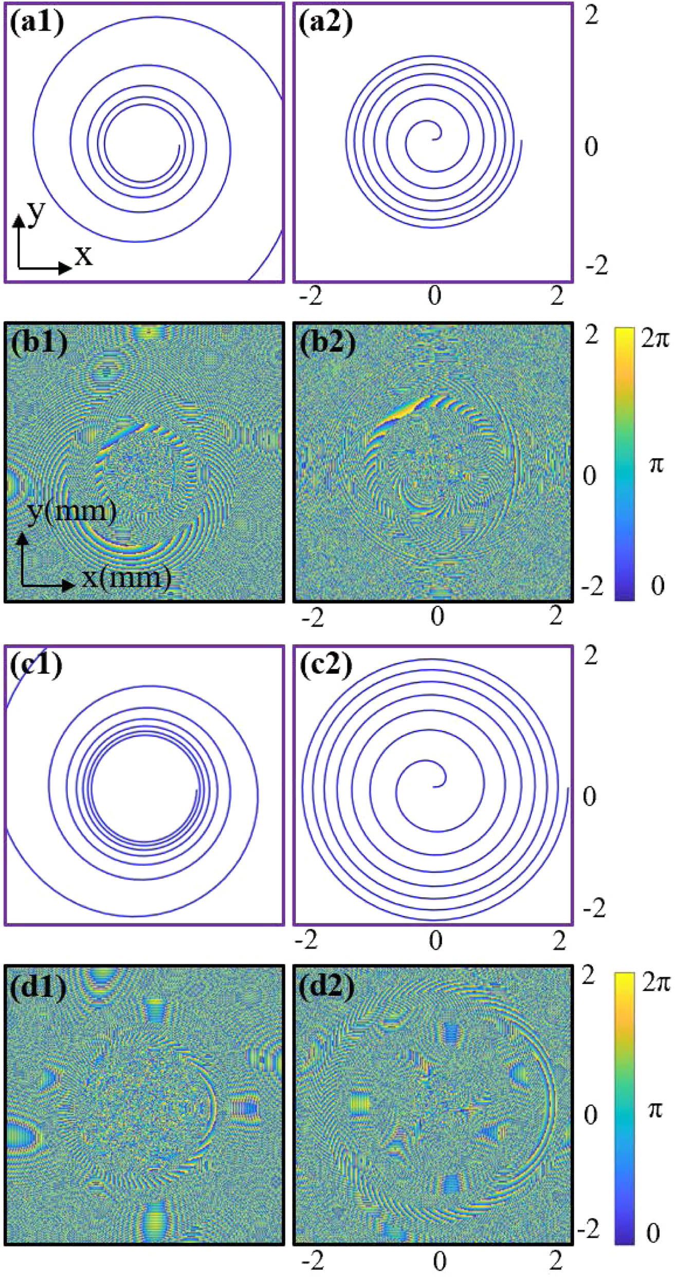
Applied to an optical geometrical transformation, the concept of Fermat’s spiral transformation from a geometric model to a physical one is outlined in Fig. 1. Figures 1(a1), 1(a2), 1(c1), and 1(c2) depict the geometry of the spiral mathematically. Meanwhile, Figs. 1(b1), 1(b2), 1(d1), and 1(d2) depict the corresponding physical patterns. The transformation parameter is in Figs. 1(a1), 1(a2), 1(b1), and 1(b2) and in Figs. 1(c1), 1(c2), 1(d1), and 1(d2). It can be seen from Figs. 1(a1) and 1(c1), which are described by Eq. (2), that the transformation phase profiles in Figs. 1(b1) and 1(d1) show a spiral shape. However, Figs. 1(a2) and 1(c2) depict a branch of Fermat’s spiral described by Eq. (4). Accordingly, the correction phase profiles in Figs. 1(b2) and 1(d2) show the shape of Fermat’s spiral. More importantly, the spiral pitch of Fermat’s spiral decreases as the number of spiral loops increases, as presented in Figs. 1(a2) and 1(c2). The inward-running spiral is mapped to the outward-running spiral in the spiral transformation. Thus, by means of Fermat’s spiral transformation, the intensity profile of the output beams theoretically exhibits a more typical donut-like shape than that in the logarithmic spiral transformation.
Figure 1.Schematic illustration of Fermat’s spiral. (a), (c) Geometric pattern. (b), (d) Phase distribution. (a1), (b1) Transformation phase and (a2), (b2) correction phase with . (c1), (d1) Transformation phase and (c2), (d2) correction phase with .
Figure 2.Numerical simulations of Fermat’s spiral transformation on vortex beams in the case of integer multiplication and division. (a) Input LG beams with . (b) Output beams while . (c) Corresponding intensity and phase of (b). (d) Output beams while . (e) Corresponding intensity and phase of (d).
In this section, we perform analyses of multiplication and division on OAM beams by Fermat’s spiral transformation. The parameters involved are , , , and with , for the multiplication while , for the division.
Here, we demonstrate the simulation results of Fermat’s spiral transformation on vortex beams in the case of integer and fraction OAM operations in Figs. 2 and 3, respectively. The final output beams are obtained by using a system to spatially filter the beams that propagate after two phase masks. In Fig. 2(a), the input OAM states are . Figure 2(b) displays the multiplication results with while Fig. 2(c) displays the corresponding intensity and phase profiles. One can clearly see that, after performing an operation on LG beams, the OAM states of the output beams are . In the other aspect, Fig. 2(d) displays the division results with while Fig. 2(e) displays the corresponding intensity and phase profiles. It is also evident that the OAM states of the output beams are after performing an operation.
Figure 3.Numerical simulations of Fermat’s spiral transformation on vortex beams in the case of fraction multiplication and division. (a) Input LG beams with . (b1), (b2) Output beams while . (b3), (b4) Output beams while . (c) Corresponding intensity and phase of (b).
Then, we turn to realize fraction OAM operations, of which numerical simulations are reported in Fig. 3. Figure 3(a) exhibits input vortex beams. After performing fraction OAM operations, Fig. 3(b) displays the output beams while Fig. 3(c) displays the corresponding intensity and phase profiles. In Figs. 3(a1) and 3(a2), input LG beams carry the topological charge , respectively. After performing an OAM multiplication with , the output OAM states are , as shown in Figs. 3(b1), 3(b2), and 3(c1)–(c4). On the other hand, input LG beams carry the topological charge of in Figs. 3(a3) and 3(a4), respectively. The output OAM states are after performing an OAM division with , as shown in Figs. 3(b3), 3(b4), and 3(c5)–(c8).
Figure 4.Phase with different transformation parameters that are applied to Figs. 2 and 3. (a1)–(d1) Transformation phase. (a2)–(d2) Correction phase. (a1), (a2) . (b1), (b2) . (c1), (c2) . (d1), (d2) .
Next, Fig. 4 presents two phase masks for several transformation parameters that are applied to OAM operations in Figs. 2 and 3. The transformation phase that maps the input intensity pattern into a Fermat’s spiral one is depicted in Figs. 4(a1)–4(d1). Figures 4(a2)–4(d2) depict the correction phase, which performs the required phase correction of both the first phase and the phase generated during the propagation. The transformation parameters of each row of Fig. 4 from top to bottom are , respectively. It can be found that the phase patterns in Fig. 4 exhibit a spiral shape. Particularly, the correction phase patterns exhibit a Fermat’s spiral shape described by Eq. (4).
Furthermore, the power weight of the output OAM modes in the case of multiplication and division is reported in Fig. 5. Since free space paraxial beams carrying OAM can be expressed as a weighted superposition of LG modes, we decompose the final output field, which has been spatially filtered by a system, into a set of LG modes to ascertain the purity included in the dominant OAM modes [43,44]. When the input OAM states are , after performing multiplication with , the power weights of the output modes, respectively, center at , as illustrated in Fig. 5(a). On the other hand, if the input OAM states are , after performing division with , the output beams obviously have the highest power at OAM modes, as illustrated in Fig. 5(b). These results indicate that, after performing OAM operations, the output OAM mode that should be obtained is significantly more weighted than the others.
At the end of this section, the optical descriptions of integer and fraction OAM operations are demonstrated in Figs. 6–8. Accordingly, the interference patterns of the output beams, which have been spatially filtered by a system, and Gaussian beams are depicted to describe the output OAM modes. First, Fig. 6 demonstrates the optical description of integer multiplication with for input LG beams carrying . Input intensity patterns and the corresponding interference patterns are shown in Figs. 6(a) and 6(b), respectively. From the interference patterns of the output beams in Fig. 6(d), it is revealed that the input OAM modes have successfully converted into the output ones with after performing multiplication with . Next, Fig. 7 demonstrates the optical description of integer division with . The interference patterns in Fig. 7(b) illustrate that the input OAM states are . The output OAM states are , as shown in the interference patterns in Fig. 7(d).
Figure 6.Optical description of integer multiplication with . (a1)–(a4) Intensity of input LG beams with . (b1)–(b4) Corresponding interference patterns of (a). (c1)–(c4) Intensity of the output beams with . (d1)–(d4) Corresponding interference patterns of (c). All images are on the same size scale.
Figure 7.Optical description of integer division with . (a1)–(a4) Intensity of input LG beams with . (b1)–(b4) Corresponding interference patterns of (a). (c1)–(c4) Intensity of the output beams with . (d1)–(d4) Corresponding interference patterns of (c). All images are on the same size scale.
Figure 8.Optical description of fraction multiplication with and division with . (a1)–(a4) Intensity of input LG beams with . (b1)–(b4) Corresponding interference patterns of (a). (c1)–(c4) Intensity of the output beams with . (d1)–(d4) Corresponding interference patterns of (c). All images are on the same size scale.
Lastly, Fig. 8 demonstrates the optical description of fraction multiplication with and division with . The interference patterns in Figs. 8(b1) and 8(b2) illustrate that the input OAM states are . The output beams shown in Figs. 8(c1) and 8(c2) have OAM modes , as illustrated in the interference patterns in Figs. 8(d1) and 8(d2). On the other hand, the input OAM states are , as shown in Figs. 8(a3), 8(a4), 8(b3), and 8(b4). After performing division with , the output OAM states are , as shown in Figs. 8(c3), 8(c4), 8(d3), and 8(d4). The optical description further confirms the expected Fermat’s spiral transformation on OAM beams, consistent well with the theoretical predictions.
4. EXPERIMENTAL RESULTS
In this section, we carry out an experiment to verify the theoretical results above. Figure 9 presents the illustration of the proof-of-principle configuration. Generated by a He–Ne laser with 633 nm wavelength, Gaussian beams propagate through a half-wave plate (HP) and a linear polarizer (Pol.). After being expanded by an objective lens (×10 objective) and a 60 mm lens (L1), the beams illuminate a transmissive spatial light modulator (RSLM1080P) (SLM1) to generate LG modes by means of computer-generated hologram. The phase is encoded in a reflective phase-only spatial light modulator (HDSLM80R-NIR) (SLM2). LG modes are projected on SLM2 to perform the transformation. The transformed beams propagate through the beams’ relaying system that consists of L2 and L3. Relying on this system, the intensity profiles in the plane of the SLM2 are recorded. Finally, we use a complementary metal oxide semiconductor camera (CMOS, CinCam CMOS-1201) to image the intensity profiles at different distances between and .
Figure 9.Schematic of the experimental setup. HP, half-wave plate; Pol.1–Pol.3, polarizer; objective, objective lens (, ); L1, 60 mm lens; SLM1, transmissive spatial light modulator; BS, beam splitter; SLM2, reflective phase-only spatial light modulator; L2 and L3, 150 mm lens; CMOS, complementary metal oxide semiconductor camera.
Figures 10 and 11 depict the evolution of input LG beams in OAM operations after illuminating the first phase mask during propagation of the distance theoretically and experimentally. In Fig. 10, the input OAM state is . Figures 10(a) and 10(c) show the simulation results while Figs. 10(b) and 10(d) show the corresponding experiment results. The evolutions of LG beams in integer multiplication with are reported in Figs. 10(a) and 10(b). One can see that the ring of the output beams is thinner than that of input LG beams owing to the extension of beams. Thus, the number of abrupt phase jumps in a period increases after performing multiplication. In the other aspect, LG beams are mapped in integer division with in Figs. 10(c) and 10(d). On the contrary, the ring of the output beams is wider than that of the input beams, and the number of abrupt phase jumps in a period decreases after performing division.
Figure 10.Evolution of input LG beams carrying in the case of integer multiplication and division. (a) Simulation results of the transverse intensity at different distances while . (b) Corresponding experiment results of (a). (c) Simulation results of the transverse intensity at different distances while . (d) Corresponding experiment results of (c).
Figure 11.Evolution of input LG beams carrying in the case of fraction multiplication and division. (a) Simulation results of the transverse intensity at different distances while . (b) Corresponding experiment results of (a). (c) Simulation results of the transverse intensity at different distances while . (d) Corresponding experiment results of (c).
Finally, we analyze the evolution of input LG beams carrying in fraction OAM operations after illuminating the first phase mask during propagation of the distance . Figures 11(a) and 11(c) present the simulation results while Figs. 11(b) and 11(d) present the corresponding experiment results. Similar to the evolution in integer OAM operations in Fig. 10, the output beams have the same characteristics. As shown in Figs. 11(a) and 11(b), the ring of the output beams is thinner than that of the input beams in fraction multiplication with for the increase of the number of abrupt phase jumps in a period. However, the ring of the output beams is wider than that of the input beams in fraction division with for the decrease of the number of abrupt phase jumps in a period. Comparing the simulation results with the experimental ones in Figs. 10 and 11, it is concluded that they are in good agreement. On the other hand, the experimental characterization that uses single-step geometric transformation for the highly accurate OAM multiplication is demonstrated [45]. Besides, metasurfaces [41] or computational optics will also provide another good experimental implementation.
5. CONCLUSION
In conclusion, we theoretically and experimentally report a Fermat’s spiral transformation scheme to operate optical multiplication and division on OAM beams. The simulation results of OAM operations are presented with integer and fraction transformation parameters . Besides, the power weight of the output OAM modes is reported to confirm the expected ability of OAM mode conversion by Fermat’s spiral transformation. Furthermore, the interference patterns of the output beams and Gaussian beams are demonstrated to characterize the output OAM modes. Finally, an experiment is carried out to investigate the evolution of the input LG beams in multiplication and division after illuminating the first phase mask during propagation of the distance and before reaching the second phase mask. As expected, the experimental results agree well with the simulation analyses, confirming the feasibility of OAM mode conversion by Fermat’s spiral transformation. We believe that our study may inspire other new ideas in performing optical geometrical operations on OAM beams and manipulating OAM states. Moreover, it offers great potential in optical communications with larger OAM modes as well as quantum state transformations in high-dimensional systems.