
Xiaotian Ji, Xingquan Zhang, Lisheng Zuo, Tao Wang, Shanbao Pei, Guotao Zhang. Precise Set for Loading Region in Numerical Simulation of Laser Shocking Peening[J]. Laser & Optoelectronics Progress, 2020, 57(5): 051404
- Laser & Optoelectronics Progress
- Vol. 57, Issue 5, 051404 (2020)
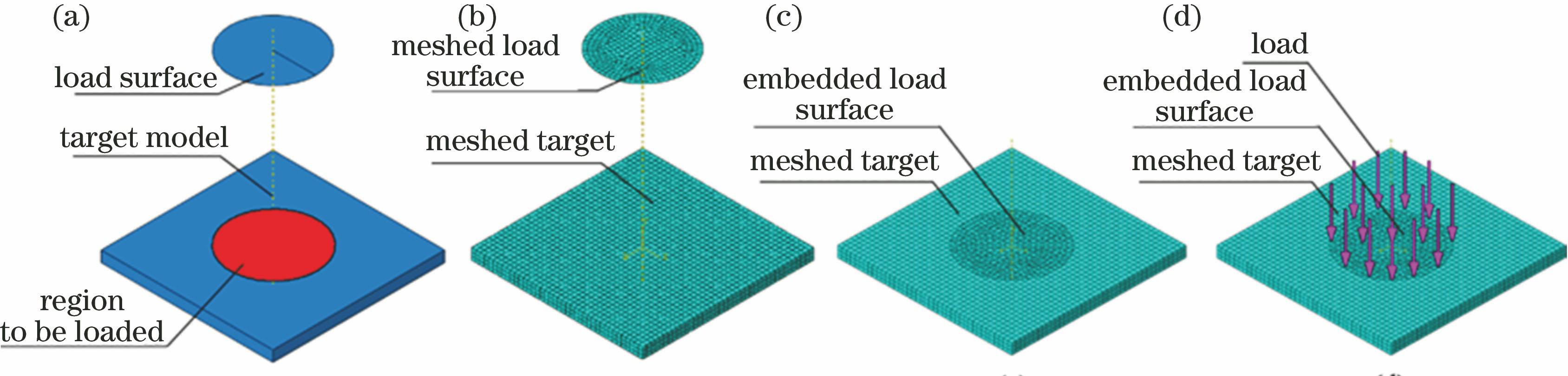
Fig. 1. Principle of load region set with embedded surface. (a) Establishment of model; (b) mesh partition; (c) embedment of load surface; (d) embedment of load
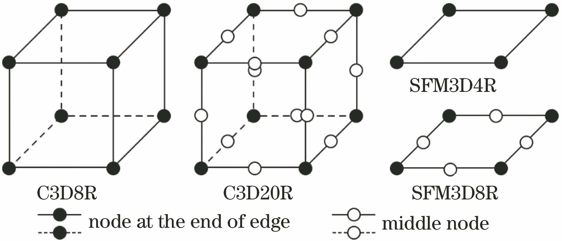
Fig. 2. Distribution of nodes in three-dimensional solid element and surface element
Fig. 3. Embedding elements of load surface and loading. (a) Model, cross-sections, and loads; (b) distribution of nodes and equivalence of load; (d) distribution of equivalent load on target
Fig. 4. Comparison between two sets for load region. (a) The set based on fitting with element surfaces; (b) the set based on embedded surface
Fig. 5. Process of loading in multi-spot laser shocking. (a) Geometrical model of target and load surface; (b) mesh for target and load surface; (c) embedding the loading surface; (d) load on spot 1; (e) load on spot 2; (f) load on spot 9
Fig. 6. Load curve for simulation example
Fig. 7. Mises stress nephogram of the set based on embedded surface. (a) Accompanied with load surface; (b) removing load surface
Fig. 8. Results of displacements of the set based on embedded surface. (a) Accompanied with load surface; (b) removing load surface
Fig. 9. Mises stress of the set of fitting with element surfaces
Fig. 10. Displacement of the set of fitting with element surfaces
Fig. 11. Shocked sample. (a) Photograph of absorbed layer; (b) photograph of sample surface; (c) morphology of selected crater
Fig. 12. Morphology and its curve of crater. (a) Measuring location; (b) cross-section profile
Fig. 13. Comparison of profiles between experiment and simulation. (a) Whole profile; (b) partial enlargement

Set citation alerts for the article
Please enter your email address
© Copyright 2018-2021 | Chinese Laser Press. All Rights Reserved 沪ICP备15018463号-20