
Libo Yuan. Multi-Core Fiber Characteristics and Its Sensing Applications[J]. Laser & Optoelectronics Progress, 2019, 56(17): 170612
- Laser & Optoelectronics Progress
- Vol. 56, Issue 17, 170612 (2019)
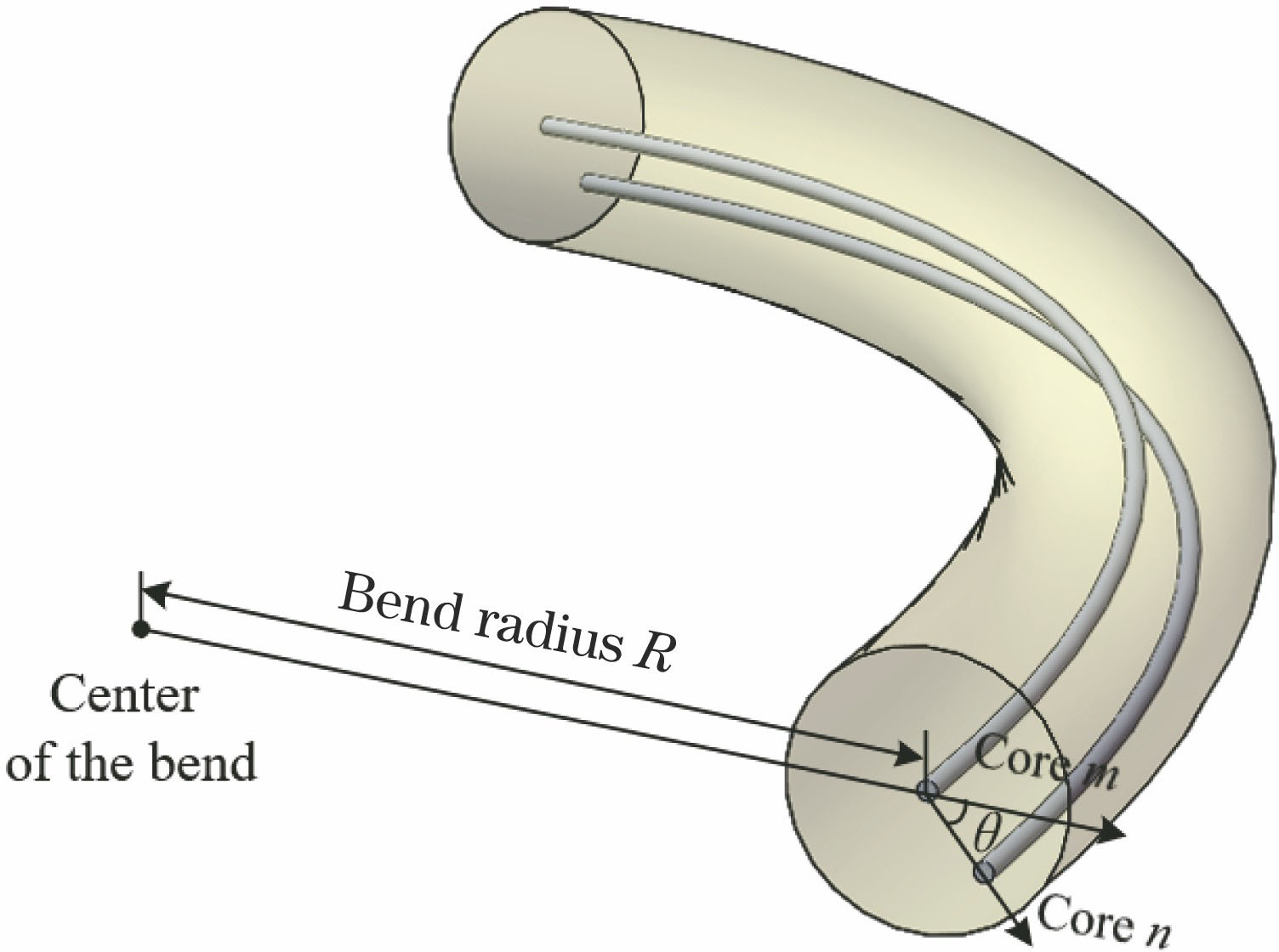
Fig. 1. Schematic of refractive index change of each core of multi-core fiber caused by bending
![Schematic of fiber prepared by suppressing inter-core crosstalk using groove refractive index profile[50-53]. (a) Refractive index distribution of single core of multi-core fiber encircled by low refractive index; (b) schematic of cross-section structure of 7-core fiber with core refractive index showed in Fig. 2(a); (c) schematic of cross-section structure of 6-core fiber isolated by groove wall with low refractive index; (d) micrograph of cross section of ultra-low crosstalk 7-core fiber corre](/richHtml/lop/2019/56/17/170612/img_2.jpg)
Fig. 2. Schematic of fiber prepared by suppressing inter-core crosstalk using groove refractive index profile[50-53]. (a) Refractive index distribution of single core of multi-core fiber encircled by low refractive index; (b) schematic of cross-section structure of 7-core fiber with core refractive index showed in Fig. 2(a); (c) schematic of cross-section structure of 6-core fiber isolated by groove wall with low refractive index; (d) micrograph of cross section of ultra-low crosstalk 7-core fiber corre
Fig. 3. Fiber prepared by circumferential assisted crosstalk suppression method[54-55]. (a) Refractive index distribution of single core of multi-core fiber encircled by air holes; (b) schematic of cross-section structure of 7-core fiber corresponding to Fig. 3(a); (c) schematic of cross-section structure of 6-core fiber isolated by air holes wall; (d) micrograph of cross section of ultra-low crosstalk 6-core fiber corresponding to Fig. 3(c)
Fig. 4. Fiber prepared by crosstalk suppression method with mismatched transfer constant of heterogeneous fiber core[23]. (a) 7-core fiber; (b) 19-core fiber
Fig. 5. Multi-core fiber with 19 cores[57]. (a) Cross section; (b) groove refractive index profile
Fig. 6. Multi-core fiber with 32 cores[58]. (a) 32-core signal transmission fiber; (b) 32-core Er/Yb-doped fiber
Fig. 7. Change of refractive index caused by bending of multi-core fiber. (a) Refractive index distribution of straight silica optical fiber; (b) effective refractive index distribution of bent silica optical fiber
Fig. 8. Low refractive index groove cladding technology. (a) Refractive index profile for each core of multi-core fiber; (b) micrograph of cross section of 7-core fiber with groove refractive index; (c) enlarged micrograph of single core
Fig. 9. Refractive index profiles n(r,θ) of cores located at different positions in multi-core fiber[54]
Fig. 10. Crosstalk between fiber cores as a function of bending radius in multi-core fiber
Fig. 11. Several splitters with multi-core fiber. (a) Space-lens-composite multi-core fiber splitter; (b) 3D waveguide multi-core fiber splitter; (c) fused tapered multi-core fiber splitter
Fig. 12. Fan-in/fan-out system for 7-core fiber based multichannel beam splitting. (a) Schematic of system; (b) cross section of splitter; (c) cross section of multi-core fiber
Fig. 13. Multi-core fiber splitting scheme based on quartz capillary stack. (a) Quartz capillary with etched single-core fibers; (b) cross-sectional view of stacked 7-core fibers
Fig. 14. Schematics of deformation of typical tapered fiber and light-field power distribtuion of core. (a) Relationship between fiber deformation and taper length; (b) schematic of light-field power distribution of tapered fiber core
Fig. 15. Schematics of two typical light splitting/coupling mechanisms based on multi-core fiber tapered coupling. (a) Multi-core fiber tapered coupling with central core; (b) multi-core fiber tapered coupling without central core
Fig. 16. Typical two-core, three-core, 4-core, and 7-core fibers with central core
Fig. 17. Typical two-core, three-core, and 4-core fibers without center core
Fig. 18. Excitation coupling characteristics of two-core fiber and single-mode fiber. (a)-(c) Physical processes of optical field coupling in fusing taper at melting point; (d) process of light-field coupling from single-mode fiber into two cores of two-core fiber through taper region; (e) energy in each core as a function of taper diameter
Fig. 19. Hollow elliptic two-core polarization-maintaining fiber and itsstructure
Fig. 20. Schematics of preparation method of hollow elliptic multi-core polarization-maintaining fiber. (a) Preparation of fiber preform; (b) preparation of fiber drawing
Fig. 21. Cross sections of three-core and four-core hollow elliptic multi-core polarization-maintaining fibers
Fig. 22. Mode characteristic curves of hollow elliptic multi-core fibers. (a) e=1, circular core; (b) d=2 μm, elliptic core
Fig. 23. Shape and structure of elliptic fiber core
Fig. 24. Birefringence characteristic curves of elliptic fiber core. (a) Circular core; (b) d=2 μm, elliptic core
Fig. 25. Typical linear-array multi-core fibers. (a) Cross-sectional structure; (b) schematic of refractive index profile; (c) cross sections of 6-core, 23-core, and dual-structure 14-core fibers
Fig. 26. Preparation method for linear-array multi-core fiber. (a) Structure of fiber perform; (b) locally enlarged photograph of core
Fig. 27. Linear-array multi-core fiber for high-power fiber lasers. (a) Rectangular-array multi-core fiber; (b) air-cladding linear-array multi-core fiber
Fig. 28. Linear-array multi-core fiber for laser output reshaping. (a) Splicing of linear-array multi-core fiber to single-mode fiber; (b) output beam after propagating 2 mm from splicing point; (c) output beam after propagating 55 mm from splicing point
Fig. 29. Ring-array multi-core fiber. (a) Cross section; (b) refractive index distribution
Fig. 30. Far-field interference patterns of bending sensor based on 4-core fiber. (a) Cross section of 4-core fiber; (b) far-field pattern at 820 μm; (c) enlarged photograph of far-field pattern
Fig. 31. Michelson interferometer based on symmetric two-core fiber[30]
Fig. 32. Far-field interference patterns of three-core fiber interferometer[92]. (a) Three-core fiber distributed in right triangle and its interference pattern; (b) three-core fiber distributed in regular triangle and its interference pattern
Fig. 33. Bending sensor based on 7-core fiber interferometer[93]
Fig. 34. High-temperature sensor based on two-core fiber[95]. (a) Micrograph of cross section of two-core fiber; (b) principle of high-temperature sensing
Fig. 35. High-temperature sensors based on 7-core and 19-core fiber interferometers[96]. (a) 7-core fiber; (b) 19-core fiber; (c) structure and principle of high-temperature sensing based on multi-core fiber interferometer
Fig. 36. SPR sensor based on two-core fiber[99]
Fig. 37. Multi-channel SPR sensor based on two-core fiber[100]
Fig. 38. Distributed measurement system of torsional 7-core fiber Bragg grating array
Fig. 39. Bending sensor based on torsional multi-core fiber. (a) 4-core sensing fiber; (b) schematic of fiber torsion; (c) fiber bending sensing; (d) monitoring of bending and position sensing in laboratory; (e) monitoring of flexible plane sensing in practical applications

Set citation alerts for the article
Please enter your email address
© Copyright 2018-2021 | Chinese Laser Press. All Rights Reserved 沪ICP备15018463号-20