
Tingting Liu, Qiang Hao, Heping Zeng. All Polarization-Maintaining Fiber-Based Frequency Combs[J]. Laser & Optoelectronics Progress, 2018, 55(12): 120003
- Laser & Optoelectronics Progress
- Vol. 55, Issue 12, 120003 (2018)
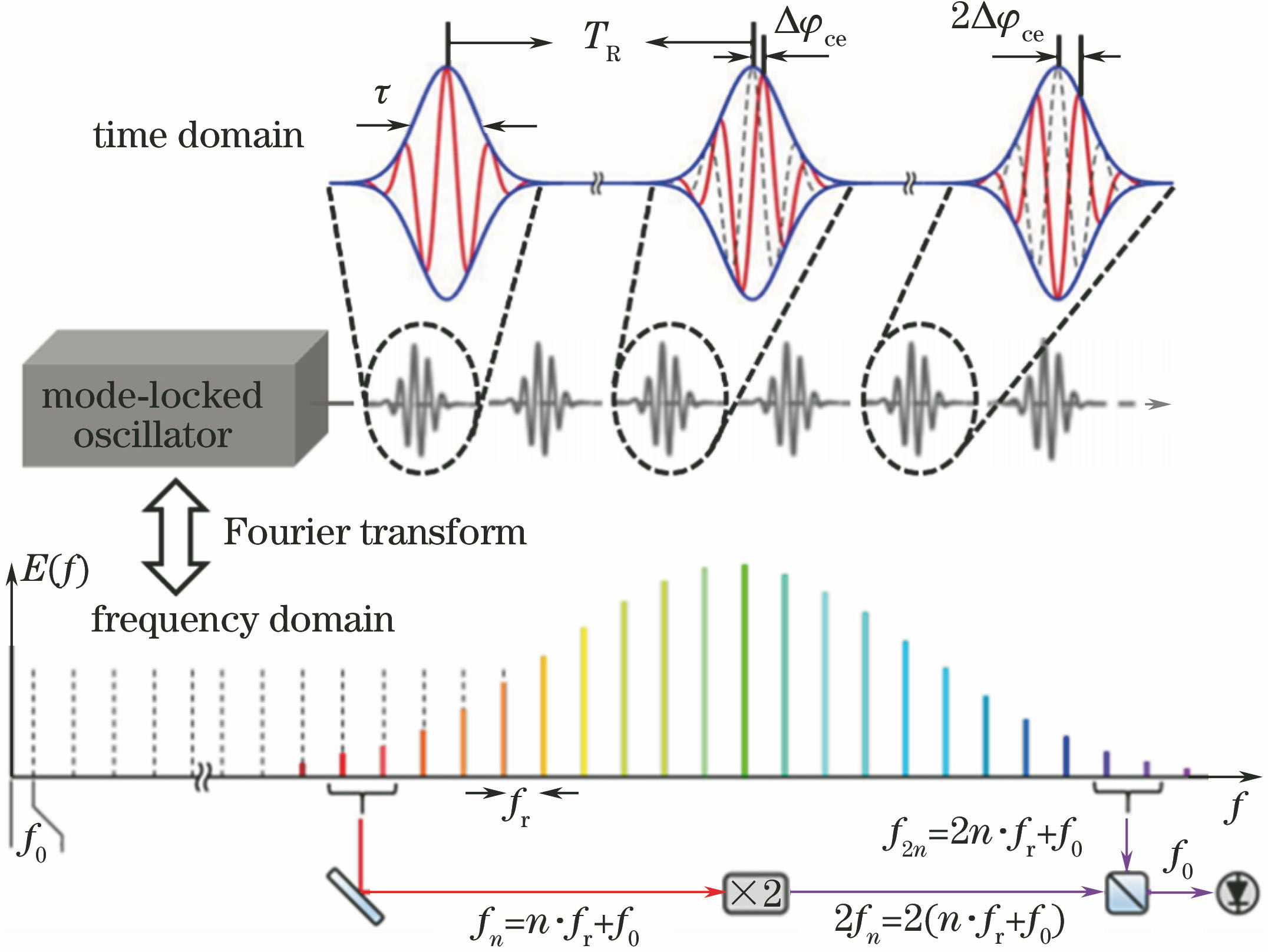
Fig. 1. Fourier transform of the mode-locked laser in time and frequency domains
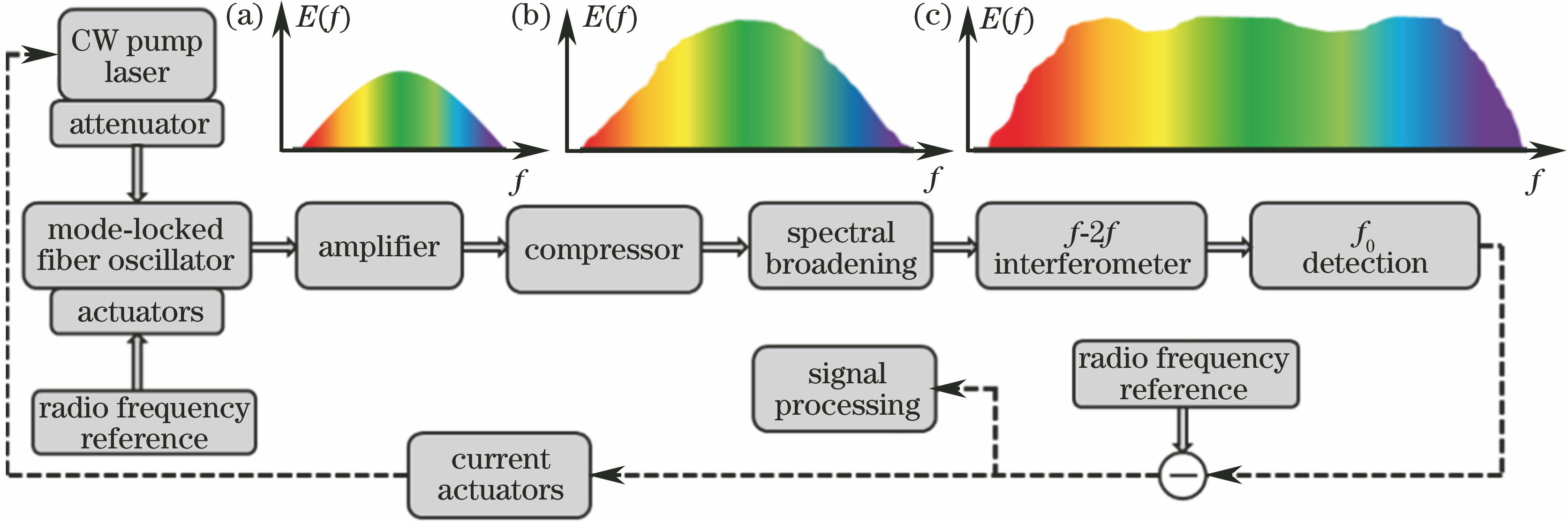
Fig. 2. Typical framework of a frequency comb. (a) Output spectrum of mode-locked laser; (b) amplifier output spectrum; (c) supercontinuum spectrum
Fig. 3. Mode-locked lasers structures of “8” cavity (a) and “9” cavity (b); the cavity losses versus the nonlinear phase shifts of “8” cavity (c) and “9” cavity (d)
Fig. 4. Experiment for locking repetive frequencies using an electronically controlled polarization controller. (a) Schematic of experimental setup; (b) frequency shift of the repetition rate versus the voltage applied on the EPC
Fig. 5. Two experimental constructions of divided-pulse amplification. (a) Structure with individual pulse divider and combiner; (b) structure with PBS and FRM
Fig. 6. Supercontinuum generation based on an Er-doped fiber laser mode-locked via NALM
Fig. 7. Structure of non-collinear f-2f interferometer
Fig. 8. Structure of collinear f-2f interferometer
Fig. 9. Operational principle diagram of AOFS

Set citation alerts for the article
Please enter your email address
© Copyright 2018-2021 | Chinese Laser Press. All Rights Reserved 沪ICP备15018463号-20