
Zhaohui Wu, Yanlei Zuo, Xiaoming Zeng, Zhaoli Li, Zhimeng Zhang, Xiaodong Wang, Bilong Hu, Xiao Wang, Jie Mu, Jingqin Su, Qihua Zhu, Yaping Dai. Laser compression via fast-extending plasma gratings[J]. Matter and Radiation at Extremes, 2022, 7(6): 064402
- Matter and Radiation at Extremes
- Vol. 7, Issue 6, 064402 (2022)
Abstract
I. INTRODUCTION
There are a variety of ways in which ultraintense lasers can be manipulated using optical techniques based on plasmas, such as plasma photonic crystals,1 plasma holograms,2,3 high-harmonic generation,4–6 frequency conversion,7–10 and laser compression.11–15 Among these techniques, plasma-based laser compression is expected to considerably extend the intensity frontier owing to the robustness of plasmas in strong laser fields. At present, backward Raman amplification (BRA)12,16,17 and strongly coupled stimulated Brillouin scattering (scSBS)13,18–20 are two promising routes to laser compression. For both BRA and scSBS, the compression is based on three-wave coupling of pump, seed, and plasma waves. The energy of a relatively long pump is scattered to a counterpropagating short seed by plasma waves—Langmuir waves or ion-acoustic waves in BRA and scSBS, respectively. Theoretical results show the possibility of producing unfocused intensities over 1017 W/cm2, which is about six orders of magnitude larger than the maximum tolerable intensity of solid-state media.
However, experimental results for both BRA and scSBS are still far from the theoretical predictions.19,21–29 For BRA, the full width at half maximum (FWHM) pump duration is compressed from ∼20 ps to ∼50 fs, but the highest transfer efficiency of 6.5% is still far from the expected value.23 For scSBS, although the transfer efficiency is close to 20%, the amplified seed intensity does not significantly exceed that of the pump, indicating that a higher laser power still cannot be obtained in this way.29
Beside technological limitations such as pulse chirp and plasma inhomogeneity encountered in experiments,30 difficulties also arise from several inherent drawbacks in the three-wave coupling model. First, it has an unwanted linear stage. In the three-wave coupling model, the plasma wave driven by the ponderomotive force of the pump and seed has to grow from near zero. The linear regime is the early stage during which the plasma wave is too weak to deplete the pump, and so the conversion efficiency is very low and the seed conversely is stretched.12 Although a strong seed enables the nonlinear stage to be reached more rapidly, this is at the cost of a reduced intensity magnification. Moreover, as the plasma wave is weak in this stage, it is vulnerable to plasma instabilities, including Landau damping, particle trapping, and thermal noise. Second, precise spatiotemporal and frequency matching of the seed and pump requires complex experimental setups. To reduce this complexity, several approaches have been proposed to avoid the need for seed preparation.31–33 However, these are still difficult to implement in practice. Third, the compression ratio (CR) is limited by plasma instabilities, in particular, modulational instability. A shorter compressed pulse can be achieved by increasing the pump intensity.12,13,18 Nevertheless, the greater plasma instability at high laser intensity imposes a limit on the extent to which the pulse duration can be reduced.
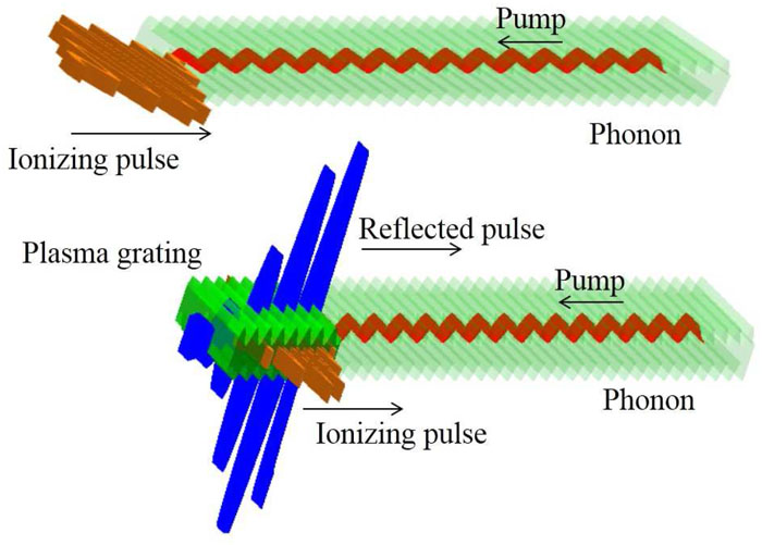
A novel approach to overcoming these problems is the use of fast-extending plasma-grating compression (FEPGC), which is shown schematically in Fig. 1. A phonon (a density wave) with spatial period half of the laser wavelength can be created by the SBS effect in a background gas. A pump pulse with an intensity below the ionization threshold first passes through the phonon region, which is possible owing due to the small Δn (where n is the refractive index) in the gas. Then, a short pulse is used to ionize the phonon, thereby creating a plasma grating expanding with the velocity of light. As Δn is much more sensitive to the plasma density than to the gas density, the resonant pump pulse is fully reflected back. It should be noted here that the reflecting surface moves with the velocity of light, and so the reflected pulse (RP) overlaps temporally with the short pulse.
![]()
Figure 1.Illustration of laser compression by a fast-extending plasma grating (FEPG) produced with a short ionizing pulse (brown pulse, cross-polarized) and a phonon (transparent green fringes) in a background gas. As the boundary of the plasma grating (green fringes) moves with the ionizing pulse, the reflected pulse (blue pulse) of the pump (red pulse) is compressed.
With an FEPGC, the plasma grating (plasma wave) is no longer produced by a pump and seed, and the compression regime in FEPGC actually involves two-wave coupling (between the pump and RP). Owing to this simplification, several key problems with plasma compression can be solved. First, the plasma grating directly inherits the large amplitude of the phonon, and so the resonant pump is transiently depleted and reflected, as a consequence of which there is no linear stage in FEPGC. Second, it is not necessary to prepare a seed, as can be seen from Fig. 1. In addition, as the plasma grating is independent of the pump, the compression can still work well at a pump intensity that is sufficiently low to avoid most laser-driven plasma instabilities. As a result, the limitations imposed on pulse duration by these instabilities can be avoided.
II. ANALYTICAL SOLUTION
To describe the compression regime, we first suppose that there is a hypersonic wave in the background gas. Ionized by a short pulse, it forms an FEPG to reflect a resonant pump. Like Bragg gratings in other media, the laser–plasma interaction in the plasma grating can be described by the coupled wave equations in the variable ζ = z/c + t as follows [the full derivation of Eq. (1) is given in the
As the plasma grating expands with the velocity of light, the boundary condition can be written as
In the nonlinear stage, ∂a/∂t in Eq. (1) can be ignored for ∂a/∂t ≪ ∂a/∂ζ.12 Substitution of the boundary conditions (2) into Eq. (1) gives
III. NUMERICAL SIMULATION
Taking hydrogen with a density wave as the background gas, the ionization and compression processes are simulated with the fully kinetic particle-in-cell (PIC) codes Opic36–38 and EPOCH. The pump has wavelength λa = 1 µm and a flat-top temporal shape. A 10T 800 nm short pulse with a peak amplitude of 0.01 is used for the ionizing pulse, where T is one optical cycle of the pump wavelength. It has crossed polarization with the pump pulse to demonstrate that it does not participate in the coupling process. The ionization is represented by an Ammosov–Delone–Krainov (ADK) tunnel ionization model. The acoustic period Λ is slightly longer than λa/2 to satisfy the Bragg condition
The simulation results obtained with Opic are displayed in Fig. 2 (similar results obtained with EPOCH are given in the
![]()
Figure 2.One-dimensional PIC simulation results for pulse compression by FEPG at
The RP spectrum shows an extremely wide range from 0.5ωa to 2ωa at t = 2000T, indicating that a short pulse of a few cycles can be supported, as shown in Fig. 2(g). The spectrum could be broadened by the effect of frequency conversion in the ionization as well as by the use of a dynamic plasma grating.10 Both of these can provide a continually varying refractive index for the RP thereby leading to a frequency shift. There are two peaks at about 0.7ω and 1.8ω, respectively. However, this phenomenon is not peculiar to FEPGC. Similar spectral peaks can be found when a short laser pulse is used to ionize a uniform background gas, as shown in Fig. 2(h). Therefore, they can be attributed mainly to frequency conversion in the gas ionization.
For a higher compressed intensity, we increase the pump amplitude from 0.002 to 0.007. As shown in Fig. 3(a), the AM grows linearly with t in the initial stage of compression, with a slope exactly matching that of the analytical solution obtained from Eq. (6). As the interaction time increases, the AM departs from the analytical line and finally tends to saturation at t > 4000T. Saturation appears earlier with a higher pump intensity, which is mainly a consequence of the increase in modulational instability with increasing laser intensity. Actually, transverse modulation can also be found in a 2D simulation when the RP grows, as shown in Fig. S2 of the
![]()
Figure 3.One-dimensional simulation results for (a) amplitude magnification and (b) compression ratio from FEPGC with various pump amplitudes. (c) Two-dimensional simulation result with
The regime is further demonstrated by 2D simulations with Opic, in which both the pump and ionizing pulses have Gaussian distributions with the same waist of 50 µm. In contrast to the 1D simulation, the ionizing pulse with a peak amplitude of 0.01 has the same polarization and wavelength as the pump. Actually, the ionizing pulse can be artificially polarized, because it does not participate in the compression process. Here, it has the same polarization as the pump to collect its energy to the RP. As shown in Fig. 3(c), the RP intensity grows to 9 × 10¹⁶ W/cm2 after t = 5500T, with a compressed FWHM duration of about 10 fs, corresponding to an AM of ∼40 and a CR of 3667. The total transfer efficiency is 35%. However, the efficiency is not uniformly distributed, with ∼90% at the beam center but only ∼10% at the edge. This is mainly due to beam divergence, which makes the edge region depart from the Bragg condition. This problem can be avoided by using a large-scale pump beam with a much smaller divergence angle. The efficiency reaches more than 60% in our simulation when 200 µm (waist) sixth-order super-Gaussian beams are employed for the pump and ionizing pulses (see the
To optimize FEPGC, a series of 1D PIC simulations are carried out with different modulation depths ρ and average plasma densities ρ0. ρ and ρ0 influence FEPGC mainly by changing the penetration depth of the pump, which is defined as the width from the pump peak to the first valley, as shown in Fig. 4(a). It is an important parameter representing the reflective feature of the plasma grating. Usually, a smaller penetration depth is expected for a shorter RP duration and higher RP intensity, indicating that higher ρ and ρ0 are preferred for FEPGC, as shown in Fig. 4(b). However, plasma instabilities also increase with increasing ρ and ρ0, leading to an earlier saturation time, as shown in Figs. 4(c) and 4(d). Above all, an FEPG with larger ρ and ρ0 has advantages for the compression of short-duration pumps. Conversely, a low plasma density and small modulation depth are more suitable for longer-time compression. For instance, the AM can still grow well at t > 8000T for ρ0 = 0.005nc, as shown in Fig. 4(d), illustrating the potential of FEPGC for laser compression from hundreds of picoseconds to a few optical cycles.
![]()
Figure 4.One-dimensional PIC simulation result for FEPGC for various
The robustness of compression is tested with inhomogeneous plasmas. Figure 5(a) shows the density profiles of two plasma gratings: one with a random density fluctuation and the other with a 500λa periodic density fluctuation, both with amplitude up to 50%ρ0. For FEPGC, the pump wavelength and plasma density have to satisfy the Bragg condition
![]()
Figure 5.One-dimensional PIC simulation results for inhomogeneous plasmas. (a) Density profiles and (b) spatial frequency intensities of plasma gratings with random or periodic density fluctuations. (c) AM and (d) RP spectra for inhomogeneous plasmas.
Several major plasma instabilities that would otherwise suppress the plasma grating can be avoided here. Kinetic effects in the plasma pose little threat, owing to the low plasma temperature. In FEPGC, the compression is just behind the ionization process, leaving little distance before the RP for plasma heating by the pump. Hence, the plasma temperature can be controlled at a very low level. This regime is quite similar to seed-ionizing31,38,39 or flying-focus40–42 BRA. Moreover, the wavebreaking is far from onset. The growth time of wavebreaking is given by
IV. PHONON GENERATION
A key precondition for compression is the presence of a hypersonic wave generated by SBS in the background gas. This has been experimentally realized and is widely used for phase conjunction45,46 and laser compression.47,48 The density modulation due to the SBS effect is usually small. However, it can be boosted by using a strong counterpropagating laser pulse to replace the weak SBS, which can be described by combining Maxwell’s equations and the Navier–Stokes equations. With slowly varying envelope approximation, the 1D equations are as follows:49
Within a short region of low-density gas, the influence of the phonon on the laser pulses can be neglected, since δn is small. Under the assumption that E0, E1, and the density wave satisfy the resonant condition, ρ/ρ0 has an analytic solution
| Gas | η (10−6 Pa s) | υ (m/s) | n | γe (10−4) | ρ/ρ0 |
|---|---|---|---|---|---|
| H2 | 8.8 | 1295 | 1.000 13 | 2.6 | 0.06I |
| CH4 | 10.8 | 440 | 1.000 44 | 8.8 | 0.47I |
| N2 | 16.6 | 334 | 1.000 30 | 6.0 | 0.28I |
Table 1. Steady-state values of ρ/ρ0 for several gases. Both laser pulses have wavelength 1 µm, the gas pressure P = 1 atm, and the temperature T = 20 °C. The laser intensity I is expressed in units of 1012 W/cm2.
Simulation results for phonon generation by two counterpropagating laser pulses are shown in Fig. 6. As the two beams symmetrically enter the simulation window, their intensity profiles overlap, as shown in Fig. 6(a). After 3 ns of interaction, the laser intensities decrease slightly as they propagate along the gas, owing to the reflection of the phonon. However, the transmissions are still more than 90%, implying that they are not strongly influenced. This is mainly due to the low gas density (1 atm pressure) and short gas length (6000λ). As well as the laser intensity, the density modulation is slightly lower at the center of the gas. However, this inhomogeneity does not affect the FEPGC, because it does not change the Bragg condition of the plasma grating. The phonon amplitude rises above 0.5 after 3 ns, which is consistent with the analytical solution, as shown in Figs. 6(b) and 6(c).
![]()
Figure 6.One-dimensional numerical simulation and analytical calculation of the phonon generated by two 3 ns counterpropagating laser pulses in 1 atm 20 °C hydrogen. (a) Simulation results for the laser intensity distribution after 3 ns. (b) Simulation results for
As well as the SBS effect, a high-frequency gas grating has been reported to be created by the interfering ionization of two intersecting ultrashort laser pulses.51 In this regime, both plasma and gas gratings are initially created by the interfering ionization. The plasma grating disappears rapidly, owing to the thermal motion of the particles, while the gas grating remains. Such a gas grating has been demonstrated by both simulation and experiment, with a ρ/ρ0 up to 0.5. It can probably also satisfy the requirements for FEPGC.
V. CONCLUSIONS
We have proposed a novel plasma-based laser compressor. The use of density modulation in a gas combined with a short ionizing pulse enables the creation of a plasma grating whose boundary moves with the velocity of light, and so the reflection of the resonant pump is compressed. In this regime, the plasma grating is generated from a gas grating rather than from density perturbations, and so the traditional three-wave coupling model of laser compression [involving stimulated Raman scattering (SRS) and SBS] is simplified to a two-wave coupling model. This method of compression has several excellent features: a high compression efficiency without a linear stage, robustness to plasma instabilities, no need for a seed, and an ultrashort compressed duration. Finally, the required density modulation can be generated by either the SBS effect or interfering ionization in the background gas.
The compression regime is similar to, although not exactly the same as the concept of a “flying mirror.” A flying mirror formed by high-velocity particles has been proposed for laser compression and x-ray generation.52 To effectively reflect the pump, the plasma density has to be overcritical
The simulation results of the fully kinetic Opic PIC code reveal that a 10–40 ps pump with a wavelength of 1 µm is compressed to a few optical cycles (7–10 fs), with a 2D transfer efficiency up to 60%. As the pulse is compressed to a few optical cycles, it can provide an extremely high-brightness source for the generation of isolated attosecond pulses. Moreover, assuming that comparable efficiency can be obtained in the 3D case, and that a 20 kJ, 20 ps, 1053 nm pump laser can be produced by Nd:glass chirped pulse amplification (CPA),53 the potential exists to produce a peak power above 1 EW (1018 W) after compression. However, as 2D simulations do not fully reveal the physical processes involved in FEPGC, 3D simulations will be required for future development of this technique.
As well as laser compression, the acoustic plasma grating proposed here provides new ways for laser manipulation. Compared with dynamic gratings in a plasma,1,54,55 the acoustic grating generated by the SBS effect in a gas is much more stable, with a reflectivity up to 95%.49 As the acoustic plasma grating is obtained directly from a gas grating, it may retain those benefits and thereby significantly enhance the quality of plasma optics.
VI. MATERIALS AND METHODS
The PIC codes Opic and EPOCH were used for the simulation of FEPGC. As the PIC code cannot describe phonon generation, we took hydrogen with a modulation period around λa/2 as the background gas. The physical processes, including optical ionization, particle motion, and the evolution of electromagnetic field, were then simulated by the PIC code based on Maxwell’s equations.
The 1D EPOCH simulation was carried out in a 3000λa static window, with 20 cells per λa and 32 particles per cell. The 1D Opic simulation used an 800-wavelength moving window, with 20 cells per λa and 32 particles per cell. The simulation results showed good consistency with each other. The 2D Opic simulation with 50 μm-waist Gaussian beams was carried out in a moving window of 300λa × 100λa, with five cells per λa longitudinally and ten cells per λa transversely, and 32 particles per cell. For the 2D Opic simulation with 200 μm-waist super-Gaussian beams, we used a moving window of 300λa × 500λa, with ten cells per λa longitudinally and 1 cell per λa transversely, and 32 particles per cell.
The simulation of phonon generation by the SBS effect in gas was based on Maxwell’s equations and the Navier–Stokes equations. The numerical solution used the split-step fast Fourier transform (SFFT) and a Runge–Kutta method. For the simulation, a static window with ten steps per λa and a total length of 6000λa was used. Hydrogen at a pressure of 1 atm and a temperature of T = 20 °C was taken as the background gas. Two counterpropagating 3 ns flat-top pulses with the same intensity of 1013 W/cm2 were taken as the interfering lasers.
SUPPLEMENTARY MATERIAL
ACKNOWLEDGMENTS
Acknowledgment. The authors gratefully acknowledge helpful discussions with Professor Nathaniel J. Fisch and Syzmen Suckewer. This work was partly supported by the National Key Program for S&T Research and Development (Grant No. 2018YFA0404804), the National Natural Science Foundation of China (Grant No. 11875240), and the Science and Technology on Plasma Physics Laboratory Fund (Grant No. 6142A0403010417).
References
[1] G.Lehmann, K. H.Spatschek. Transient plasma photonic crystals for high-power lasers. Phys. Rev. Lett., 116, 225002(2016).
[2] L.Chopineau, A.Denoeud, A.Leblanc, P.Martin, G.Mennerat, F.Quéré. Plasma holograms for ultrahigh-intensity optics. Nat. Phys., 13, 440(2017).
[3] I. Y.Dodin, N. J.Fisch. Storing, retrieving, and processing optical information by Raman backscattering in plasmas. Phys. Rev. Lett., 88, 165001(2002).
[4] C. G. Durfee, T. J.McIlrath, H. M.Milchberg. High-order frequency conversion in the plasma waveguide. Phys. Rev. Lett., 75, 2494(1995).
[5] P.Audebert, M.Bougeard, T.Ceccotti, P.d’Oliveira, J.-P.Geindre, A.Levy, R.Marjoribanks, P.Martin, P.Monot, F.Quéré, F.Réau, C.Thaury. Plasma mirrors for ultrahigh-intensity optics. Nat. Phys., 3, 424-429(2007).
[6] R.Clarke, B.Dromey, A.Gopal, H.Habara, S.Karsch, R.Kodama, K.Krushelnick, K.Lancaster, S.Moustaizis, D.Neely, P.Norreys, C.Stoeckl, M.Tampo, M.Tatarakis, N.Vakakis, M. S.Wei, M.Zepf. High harmonic generation in the relativistic limit. Nat. Phys., 2, 456-459(2006).
[7] Y.Avitzour, I.Geltner, S.Suckewer. Picosecond pulse frequency upshifting by rapid free-carrier creation in ZnSe. Appl. Phys. Lett., 81, 226(2002).
[8] M. R.Edwards, N. J.Fisch, Q.Jia, K.Qu. Theory of electromagnetic wave frequency upconversion in dynamic media. Phys. Rev. E, 98, 023202(2018).
[9] A. S.Davies, P.Franke, D. H.Froula, A. J.Howard, J. P.Palastro, D.Turnbull. Photon acceleration in a flying focus. Phys. Rev. Lett., 123, 124801(2019).
[10] H.Peng, C.Riconda, S. C.Ruan, S.Weber, C. T.Zhou. Frequency conversion of lasers in a dynamic plasma grating. Phys. Rev. Appl., 15, 054053(2021).
[11] Z.-M.Sheng, H.-C.Wu, J.Zhang. Chirped pulse compression in nonuniform plasma Bragg gratings. Appl. Phys. Lett., 87, 201502(2005).
[12] N. J.Fisch, V. M.Malkin, G.Shvets. Fast compression of laser beams to highly overcritical powers. Phys. Rev. Lett., 82, 4448-4451(1999).
[13] A. A.Andreev, C.Riconda, V. T.Tikhonchuk, S.Weber. Short light pulse amplification and compression by stimulated Brillouin scattering in plasmas in the strong coupling regime. Phys. Plasmas, 13, 053110(2006).
[14] F.Ewald, J.Faure, Y.Glinec, T.Hosokai, S.Kiselev, V.Malka, A.Pukhov, J.-P.Rousseau, J. J.Santos. Observation of laser-pulse shortening in nonlinear plasma waves. Phys. Rev. Lett., 95, 205003(2005).
[15] C.Bellei, C.Kamperidis, S.Kneip, S. P. D.Mangles, S. R.Nagel, Z.Najmudin, C. A. J.Palmer, P. P.Rajeev, J.Schreiber, M. J. V.Streeter. Complete temporal characterization of asymmetric pulse compression in a laser wakefield. Phys. Rev. Lett., 105, 235003(2010).
[16] N. J.Fisch, V. M.Malkin, G.Shvets. Detuned Raman amplification of short laser pulses in plasma. Phys. Rev. Lett., 84, 1208-1211(2000).
[17] R.Bingham, R. A.Cairns, F.Fiúza, R. A.Fonseca, P. A.Norreys, L. O.Silva, R. M. G. M.Trines. Simulations of efficient Raman amplification into the multipetawatt regime. Nat. Phys., 7, 87-92(2011).
[18] J.Fuchs, L.Lancia, J. R.Marquès, G. A.Mourou, C.Riconda, S.Weber. Amplification of ultrashort laser pulses by Brillouin backscattering in plasmas. Phys. Rev. Lett., 111, 055004(2013).
[19] A.Castan, A.Chatelain, M.Chiaramello, A.Frank, J.Fuchs, T.Gangolf, A.Giribono, L.Lancia, J. R.Marquès, M. N.Quinn, C.Riconda, L.Vassura, S.Weber. Signatures of the self-similar regime of strongly coupled stimulated Brillouin scattering for efficient short laser pulse amplification. Phys. Rev. Lett., 116, 075001(2016).
[20] H.Peng, J. Q.Su, Z. H.Wu, Z. M.Zhang, K. N.Zhou, Y. L.Zuo. Single laser pulse compression via strongly coupled stimulated Brillouin scattering in plasma. Phys. Plasmas, 23, 073516(2016).
[21] W.Cheng, D. S.Clark, N. J.Fisch, Y.Ping, S.Suckewer. Amplification of ultrashort laser pulses by a resonant Raman scheme in a gas-jet plasma. Phys. Rev. Lett., 92, 175007(2004).
[22] Y.Avitzour, W.Cheng, N. J.Fisch, M. S.Hur, Y.Ping, S.Suckewer, J. S.Wurtele. Reaching the nonlinear regime of Raman amplification of ultrashort laser pulses. Phys. Rev. Lett., 94, 045003(2005).
[23] W.Cheng, S.Li, J.Ren, S.Suckewer. A new method for generating ultraintense and ultrashort laser pulses. Nat. Phys., 3, 732-736(2007).
[24] S.Li, A.Morozov, S.Suckewer, D.Turnbull. Possible origins of a time-resolved frequency shift in Raman plasma amplifiers. Phys. Plasmas, 19, 073103(2012).
[25] S.Li, A.Morozov, S.Suckewer, D.Turnbull. Simultaneous stimulated Raman, Brillouin, and electron-acoustic scattering reveals a potential saturation mechanism in Raman plasma amplifiers. Phys. Plasmas, 19, 083109(2012).
[26] C.Aniculaesei, E.Brunetti, C.Ciocarlan, S.Cipiccia, J. M.Dias, B.Ersfeld, J. P.Farmer, D. W.Grant, P.Grant, R.Heathcote, M. S.Hur, D. A.Jaroszynski, N.Lemos, P.Lepipas, C. L. S.Lewis, G. G.Manahan, G.Nersisyan, A.Pukhov, G.Raj, D.Reboredo Gil, A.Subiel, G.Vieux, G. H.Welsh, S. M.Wiggins, X.Yang, S. R.Yoffe. An ultra-high gain and efficient amplifier based on Raman amplification in plasma. Sci. Rep., 7, 2399(2017).
[27] Q.Chen, A.Morozov, S.Suckewer, Z.Wu. Stimulated Raman backscattering amplification with a low-intensity pump. Phys. Plasmas, 26, 103111(2019).
[28] P.Antici, P.Audebert, J.Fuchs, A.Héron, S.Hüller, L.Lancia, A.Manci?, J. R.Marquès, M.Nakatsutsumi, C.Riconda, V. T.Tikhonchuk, S.Weber. Experimental evidence of short light pulse amplification using strong-coupling stimulated Brillouin scattering in the pump depletion regime. Phys. Rev. Lett., 104, 025001(2010).
[29] F.Amiranoff, R. L.Berger, M.Blecher, S.Bolanos, M.Chiaramello, J.Fuchs, T.Gangolf, L.Lancia, J.-R.Marqués, C.Riconda, S.Weber, O.Willi. Joule-level high-efficiency energy transfer to subpicosecond laser pulses by a plasma-based amplifier. Phys. Rev. X, 9, 021008(2019).
[30] N. J.Fisch, N. A.Yampolsky. Limiting effects on laser compression by resonant backward Raman scattering in modern experiments. Phys. Plasmas, 18, 056711(2011).
[31] N. J.Fisch, V. M.Malkin. Backward Raman amplification of ionizing laser pulses. Phys. Plasmas, 8, 4698(2001).
[32] I.Barth, N. J.Fisch, K.Qu. Plasma wave seed for Raman amplifiers. Phys. Rev. Lett., 118, 164801(2017).
[33] A. A.Balakin, D. S.Levin, S. A.Skobelev. Compression of laser pulses due to Raman amplification of plasma noises. Phys. Rev. A, 102, 013516(2020).
[34] W. L.Kruer. The Physics of Laser Plasma Interactions(1988).
[35] W.Cheng. Reaching the nonlinear regime of the Raman amplification of ultrashort laser pulses(2010).
[36] X. T.He, Z. M.Sheng, M. Y.Yu, Z. M.Zhang. Hundreds MeV monoenergetic proton bunch from interaction of 1020–21 W/cm2 circularly polarized laser pulse with tailored complex target. Appl. Phys. Lett., 100, 134103(2012).
[37] Y. Q.Gu, S. K.He, W.Hong, J.Teng, M. Y.Yu, B.Zhang, Z. M.Zhang. Envelope matching for enhanced backward Raman amplification by using self-ionizing plasmas. Phys. Plasmas, 21, 123109(2014).
[38] Z. G.Deng, Y. Q.Gu, S. K.He, W.Hong, J.Teng, B.Zhang, Z. M.Zhang, W. M.Zhou. Generation of high-power few-cycle lasers via Brillouin-based plasma amplification. Phys. Plasmas, 24, 113104(2017).
[39] D. S.Clark, N. J.Fisch. Regime for a self-ionizing Raman laser amplifier. Phys. Plasmas, 9, 2772(2002).
[40] S.Bucht, A.Davies, D. H.Froula, D.Haberberger, T.Kessler, J. L.Shaw, D.Turnbull. Raman amplification with a flying focus. Phys. Rev. Lett., 120, 024801(2018).
[41] S.-W.Bahk, I. A.Begishev, R.Boni, S.Bucht, A. S.Davies, D. H.Froula, D.Haberberger, J.Katz, T. J.Kessler, J. P.Palastro, J. L.Shaw, D.Turnbull. Spatiotemporal control of laser intensity. Nat. Photonics, 12, 262-268(2018).
[42] O.Gobert, F.Quéré, A.Sainte-Marie. Controlling the velocity of ultrashort light pulses in vacuum through spatio-temporal couplings. Optica, 4, 1298-1304(2017).
[43] D. W.Forslund, J. M.Kindel, E. L.Lindman. Theory of stimulated scattering processes in laser-irradiated plasmas. Phys. Fluids, 18, 1002(1975).
[44] S.Hüller, P.Mulser, A. M.Rubenchik. Nonstationary stimulated Brillouin backscattering. Phys. Fluids B, 3, 3339(1991).
[45] I. D.Carr, D. C.Hanna. Performance of a Nd:YAG oscillator/ampflifier with phase-conjugation via stimulated Brillouin scattering. Appl. Phys. B: Lasers Opt., 36, 83-92(1985).
[46] H. J.Eichler, H.Meng. Nd:YAG laser with a phase-conjugating mirror based on stimulated Brillouin scattering in SF6 gas. Opt. Lett., 16, 569-571(1991).
[47] V. A.Gorbunov, S. B.Paperny?, V. F.Petrov, V. R.Startsev. Time compression of pulses in the course of stimulated Brillouin scattering in gases. Sov. J. Quantum Electron., 13, 900(1983).
[48] F.Gyger, L.Thévenaz, F.Yang. Intense Brillouin amplification in gas using hollow-core waveguides. Nat. Photonics, 14, 700-708(2020).
[49] V.Babin, M.Damzen, A.Mocofanescu, V.Vlad. Stimulated Brillouin Scattering: Fundamentals and Applications(2003).
[50] D.Feldmann, H.Rottke, K. H.Welge, B.Wolff. Multiphoton-ionization of hydrogen atoms in intense laser fields. Z. Phys. D: At., Mol. Clusters, 10, 35-43(1988).
[51] C.-K.Huang, C.Joshi, K. A.Marsh, Z.Nie, M.Sinclair, Y.Wu, C.Zhang. Ionization induced plasma grating and its applications in strong-field ionization measurements. Plasma Phys. Controlled Fusion, 63, 095011(2021).
[52] S. V.Bulanov, T. Z.Esirkepov, M.Kando, A. S.Pirozhkov, N. N.Rosanov. Relativistic mirrors in plasmas. Novel results and perspectives. Phys.-Usp., 56, 429(2013).
[53] N. J.Fisch, E. A.Khazanov, B.Le Garrec, V. M.Malkin, G. A.Mourou, A. M.Sergeev, T.Tajima, Z.Toroker. Exawatt-zettawatt pulse generation and applications. Opt. Commun., 285, 720-724(2012).
[54] M.Grech, H.Peng, C.Riconda, S.Weber, C.-T.Zhou. Dynamical aspects of plasma gratings driven by a static ponderomotive potential. Plasma Phys. Controlled Fusion, 62, 115015(2020).
[55] M.Grech, H.Peng, C.Riconda, J. Q.Su, S.Weber. Nonlinear dynamics of laser-generated ion-plasma gratings: A unified description. Phys. Rev. E, 100, 061201(R)(2019).


Set citation alerts for the article
Please enter your email address

© Copyright 2018-2021 | Chinese Laser Press. All Rights Reserved 沪ICP备15018463号-20