• Opto-Electronic Advances
  • Vol. 6, Issue 6, 220178 (2023)
Yan Xing1, Xing-Yu Lin1, Lin-Bo Zhang1, Yun-Peng Xia2, Han-Le Zhang1, Hong-Yu Cui1, Shuang Li2, Tong-Yu Wang1, Hui Ren2, Di Wang1, Huan Deng2, and Qiong-Hua Wang1、*
Author Affiliations
  • 1School of Instrumentation and Optoelectronic Engineering, Beihang University, Beijing 100191, China
  • 2College of Electronics and Information Engineering, Sichuan University, Chengdu 610065, China
  • show less
    DOI: 10.29026/oea.2023.220178 Cite this Article
    Yan Xing, Xing-Yu Lin, Lin-Bo Zhang, Yun-Peng Xia, Han-Le Zhang, Hong-Yu Cui, Shuang Li, Tong-Yu Wang, Hui Ren, Di Wang, Huan Deng, Qiong-Hua Wang. Integral imaging-based tabletop light field 3D display with large viewing angle[J]. Opto-Electronic Advances, 2023, 6(6): 220178 Copy Citation Text show less
    Schematic of the proposed tabletop light field 3D display. (a) Structure of the integral imaging-based tabletop light field 3D display. (b) Principle of the modulation of the compound lens array and the light shaping diffuser screen to achieve a large viewing angle.
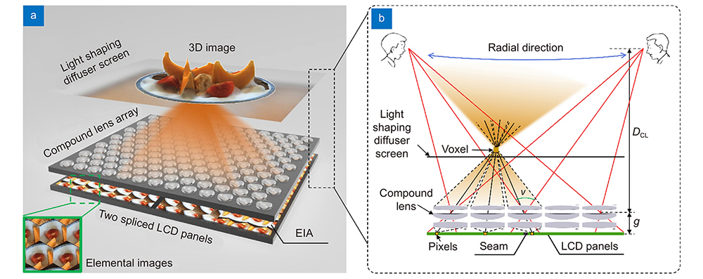
    Fig. 1. Schematic of the proposed tabletop light field 3D display. (a) Structure of the integral imaging-based tabletop light field 3D display. (b) Principle of the modulation of the compound lens array and the light shaping diffuser screen to achieve a large viewing angle.
    Designed compound lens array. (a) Schematic of the compound lens array. (b) Front and section views of the compound lens unit. Each compound lens unit consists of three spherical lenses with different materials and different surfaces. (c) Spot diagram of the compound lens unit.
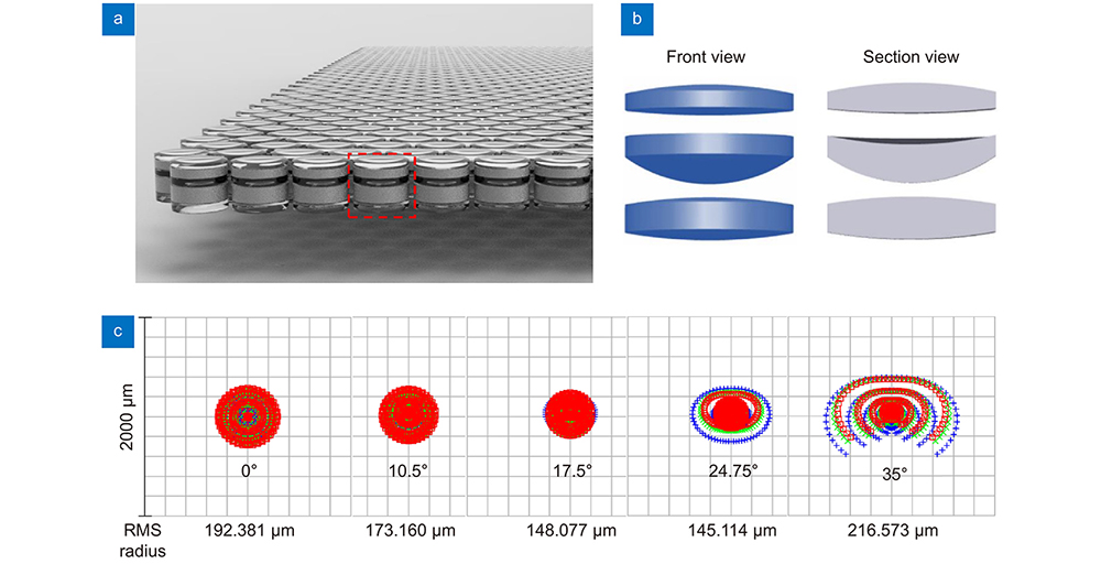
    Fig. 2. Designed compound lens array. (a) Schematic of the compound lens array. (b) Front and section views of the compound lens unit. Each compound lens unit consists of three spherical lenses with different materials and different surfaces. (c) Spot diagram of the compound lens unit.
    Schematic of the light field capture model and the backward ray tracing-based capture principle for the proposed tabletop light field 3D display. (a) Schematic of the simplified light field capture system. Each pinhole collects a pinhole image as an elemental image on the image sensor. From another perspective, each camera at the viewpoint plane captures a sub-image to simulate the viewers’ eyes. (b) Corresponding parallelogram-shaped plenoptic map. (c) Schematic of the backward ray-tracing capture. Rays are fired from the viewpoint, through the sub-image plane, and into the 3D scene.
    Fig. 3. Schematic of the light field capture model and the backward ray tracing-based capture principle for the proposed tabletop light field 3D display. (a) Schematic of the simplified light field capture system. Each pinhole collects a pinhole image as an elemental image on the image sensor. From another perspective, each camera at the viewpoint plane captures a sub-image to simulate the viewers’ eyes. (b) Corresponding parallelogram-shaped plenoptic map. (c) Schematic of the backward ray-tracing capture. Rays are fired from the viewpoint, through the sub-image plane, and into the 3D scene.
    Example of the distortion correction by performing projective transformations. All the projective transformations are performed to the sub-EIAs or the elemental images. (a) Step 1: rough correction for the whole 3D image. By performing the projective transformation to sub-EIAs 1 and 2, reconstructed 3D sub-images 1, 2, and the reference square pattern sheet match roughly. (b) Step 2: precise correction for the image of each compound lens unit. The reconstructed crosshair images through LCD panels 1 and 2 and the reference crosshair pattern sheet match precisely by using an interactive feedback program.
    Fig. 4. Example of the distortion correction by performing projective transformations. All the projective transformations are performed to the sub-EIAs or the elemental images. (a) Step 1: rough correction for the whole 3D image. By performing the projective transformation to sub-EIAs 1 and 2, reconstructed 3D sub-images 1, 2, and the reference square pattern sheet match roughly. (b) Step 2: precise correction for the image of each compound lens unit. The reconstructed crosshair images through LCD panels 1 and 2 and the reference crosshair pattern sheet match precisely by using an interactive feedback program.
    Prototype of the tabletop light field 3D display. (a) Photograph of the display prototype with displaying 3D images. (b) Photograph of the display prototype without displaying 3D images. (c) Nine 3D images from different perspectives along the circumferential direction. The circumferential perspective and parallax are correct. (d) Five 3D images taken from different angles between −34.4° and 34.3° in the radial direction. Our tabletop light field 3D display produces perspective-correct images for viewpoints in the radial direction.
    Fig. 5. Prototype of the tabletop light field 3D display. (a) Photograph of the display prototype with displaying 3D images. (b) Photograph of the display prototype without displaying 3D images. (c) Nine 3D images from different perspectives along the circumferential direction. The circumferential perspective and parallax are correct. (d) Five 3D images taken from different angles between −34.4° and 34.3° in the radial direction. Our tabletop light field 3D display produces perspective-correct images for viewpoints in the radial direction.
    Images of the USAF resolution test chart at different viewing positions in the circumferential direction. The radial viewing positions are fixed at 30°. (a) Images taken at 0°, 40°, 90°, and 130° and the zoomed-in images to illustrate the resolution. Dashed boxes denote the clear resolution of Element 6, Group −2 at 0°, 40°, and 90°, as well as Element 1, Group −1 at 130°. (b) Images taken at 180°, 220°, 270°, and 310° and the zoomed-in images to illustrate the resolution. At four viewing positions, the patterns of Element 1, Group −1 can be clearly resolved.
    Fig. 6. Images of the USAF resolution test chart at different viewing positions in the circumferential direction. The radial viewing positions are fixed at 30°. (a) Images taken at 0°, 40°, 90°, and 130° and the zoomed-in images to illustrate the resolution. Dashed boxes denote the clear resolution of Element 6, Group −2 at 0°, 40°, and 90°, as well as Element 1, Group −1 at 130°. (b) Images taken at 180°, 220°, 270°, and 310° and the zoomed-in images to illustrate the resolution. At four viewing positions, the patterns of Element 1, Group −1 can be clearly resolved.
    Images of the USAF resolution test chart at the 0° viewing position. (a) Results of the 0° viewing position directly above the display. The circumferential and radial viewing positions are both 0°. (b) Zoomed-in image.
    Fig. 7. Images of the USAF resolution test chart at the 0° viewing position. (a) Results of the 0° viewing position directly above the display. The circumferential and radial viewing positions are both 0°. (b) Zoomed-in image.
    Yan Xing, Xing-Yu Lin, Lin-Bo Zhang, Yun-Peng Xia, Han-Le Zhang, Hong-Yu Cui, Shuang Li, Tong-Yu Wang, Hui Ren, Di Wang, Huan Deng, Qiong-Hua Wang. Integral imaging-based tabletop light field 3D display with large viewing angle[J]. Opto-Electronic Advances, 2023, 6(6): 220178
    Download Citation