
Yan Xing, Xing-Yu Lin, Lin-Bo Zhang, Yun-Peng Xia, Han-Le Zhang, Hong-Yu Cui, Shuang Li, Tong-Yu Wang, Hui Ren, Di Wang, Huan Deng, Qiong-Hua Wang. Integral imaging-based tabletop light field 3D display with large viewing angle[J]. Opto-Electronic Advances, 2023, 6(6): 220178
- Opto-Electronic Advances
- Vol. 6, Issue 6, 220178 (2023)
Abstract
Introduction
Three-dimensional (3D) display is one of the most promising displays that provide realistic 3D images and has the potential to revolutionize consumer electronics used in entertainment, education, healthcare, manufacturing, and beyond
To obtain a good 3D tabletop viewing experience, the following requirements must be satisfied. Firstly, the 3D viewing angle in the radial direction should be large enough so that viewers can properly see 3D objects from large oblique viewing positions around the table. Since the 3D viewing angle of 360° in the circumferential direction is the most basic requirement for the tabletop 3D displays, the viewing angle in this direction can be ignored. Secondly, correct perspective and parallax in the radial direction should be provided so that the image perspective changes correctly as viewers move forward and backward. Thirdly, the number of viewers should not be limited. In other words, the 3D images should be seen by multiple viewers simultaneously, no matter how many viewers in the space. Finally, the viewers should not wear special glasses or headsets. And the tracking scheme should not be adopted because it will limit the number of viewers
The above four requirements should be satisfied at the same time. Among them, the first and second requirements are the most important. Holographic display
Integral imaging is a kind of light field display technology that provides an improved solution for the tabletop 3D display, and it can satisfy the last three conditions simultaneously due to several advantages in principle
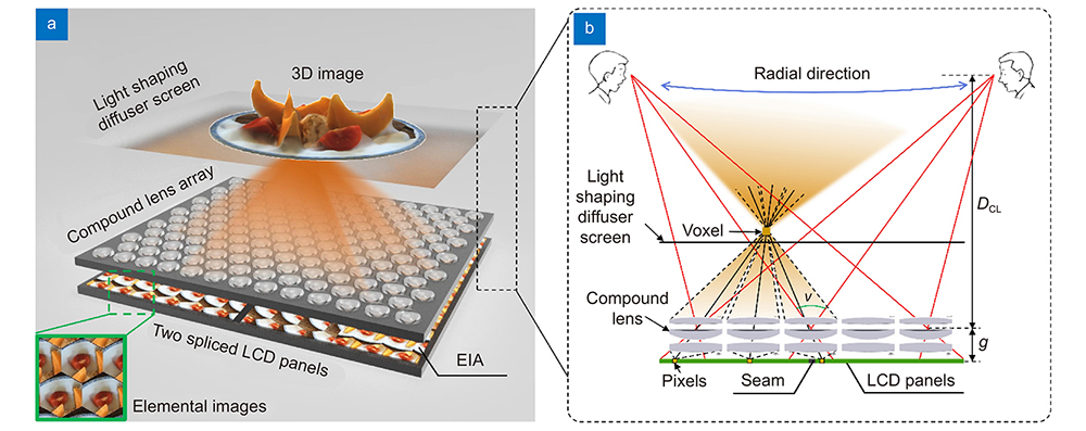
In this paper, we propose an integral imaging-based tabletop light field 3D display with a large radial 3D viewing angle in the case of a large display size. A compound lens array is designed to greatly extend the radial 3D viewing angle in the case of a limited amount of spatial information while balancing other important 3D display parameters. A new light field capture model is developed to guide the generation of EIAs based on backward ray-tracing technology. Additionally, a new method for correcting the distortion of 3D images is proposed to obtain high-quality 3D images. A 43.5-inch prototype is developed, and the radial 3D viewing angle ranges from −34.4° to 34.3°, which is larger than the conventional tabletop 3D displays. High-resolution 3D images can be observed at large radial 3D viewing positions.
Methods
The proposed tabletop light field 3D display for producing the 3D images in a larger viewing angle range is schematically shown in
![]()
Figure 1.
The 8K LCD panels display the EIA which consists of multiple periodically arranged elemental images. Each elemental image corresponds to a compound lens unit above it. Divergent LED light uniformly illuminates the pixels of the LCD panels. The emergent beam from the pixels is modulated by the corresponding compound lens unit, and sharp spots are then imaged on the plane of the light shaping diffuser screen. As shown in
As for the light shaping diffuser screen, it diffuses the light emerging from the voxels, thereby resolving the gap issue between adjacent lens units. The diffusing angles in the horizontal and radial directions are identical due to the full-parallax property of integral imaging. We choose off-the-shelf diffusers because they are convenient and inexpensive.
The overall 3D viewing angle of the tabletop light field 3D display is the overlapped angle of all the lens units’ viewing angles. In the proposed tabletop light field 3D display, the viewing angles of all lens units are converged to the center to ensure a maximum overlapped viewing angle. Since each designed compound lens has an enhanced field of view with good image quality, the overall 3D viewing angle in the radial direction is increased. In addition, the diffusion effect of the light shaping diffuser screen makes the 3D viewing angle exceed σ, where σ denotes the diffusing angle. The overall 3D viewing angle in the radial direction can be denoted as
where p is the pitch of the compound lens array, g is the distance between the planes of LCD panel and compound lens array, and DCL is the distance between the viewpoints and compound lens array planes.
Design of the compound lens array
The tabletop light field 3D display needs a large 3D viewing angle in the radial direction to ensure that correct and high-quality 3D images can be seen from large oblique viewing positions. However, the design of the lens array for the large 3D viewing angle is challenging. The reasons are as follows.
Firstly, the 3D viewing angle is determined by the pitch p of the lens array and the gap g between the lens array and the LCD panel, as depicted in equation (1). Larger pitch p and smaller gap g can improve the 3D viewing angle. In other words, lenses with a large relative aperture are required to improve the 3D viewing angle. However, the other two important 3D display parameters of spatial resolution and depth of field will significantly deteriorate in this case. The relationship between the spatial resolution, the depth of field, and the 3D viewing angle is expressed as
where RI and Rd represent the spatial resolutions of the 3D image and the LCD panel, respectively, and Zdepth represents the depth of field.
Secondly, the whole size of the lens array for display purposes is about 43.5 inches. In consideration of the weight, flatness, cost, and alignment difficulty in the fabrication of this large-size lens array, increasing the number of lenses in a lens unit for correcting aberrations does not always work. Product reliability and implementation difficulty should also be considered.
Here, we design a compound lens array composed of three-piece compound lens units. The structure of the compound lens array is shown in
![]()
Figure 2.
Light field capture model
The 3D videos displayed on the proposed tabletop light field 3D display need to be made by capturing the light field. We present a new light field capture model for the proposed tabletop light field 3D display, in which a parallelogram-shaped plenoptic map is formed, and a backward ray tracing is applied to capture the sampled plenoptic field in only one step without pixel redundancy and computing burden.
For capturing the light field, the capture system is inverse to the display. It can be schematized through a simple system in which a pinhole array is set parallel to an image sensor like a CCD. In other words, the compound lens array is simplified to a pinhole array, so we only consider rays passing through the center of the lens. In the scheme of
![]()
Figure 3.
According to the viewpoint capture theory, multiple cameras are used to simulate the viewers’ eyes by capturing the 3D scenes from viewpoints rather than lenses. One camera is shown in
This viewpoint-based system captures a sampled version of the plenoptic field. The plenoptic map at the plane of the image sensor can be represented by a 4D plenoptic function L(x, y,θ, φ) parametrizing the pinholes (x, y) on the pinhole plane and the angular inclination (θ, φ) of the rays
From another perspective, the 4D plenoptic function can also be represented by L'(m, n,x, y) parametrizing the cameras (m, n) on the viewpoint plane and the pinholes (x, y) on the pinhole plane. For a camera (m0, n0), its corresponding sampled plenoptic component is given by
where I and J are the numbers of the pinholes in the horizontal and vertical directions, respectively. It is apparent that for one camera, only the rays passing through the pinholes are useful for the pixels on the image sensor due to the sampling period p from the plenoptic map. However, the resolution of the images taken by the cameras is generally very high. More than 95% of pixels do not contribute to the EIA, so they are redundant. Therefore, the backward ray-tracing technology
Each viewpoint only shoots I × J rays which are identical to the number of pinholes. Note that the rays pointing to the physical seam do not need to be created because there are no pixels on the seam. In the ray-tracing process, the created ray may hit an object along its propagation, as shown in
Distortion correction
In the display, the reconstructed 3D images have spatial distortions, including geometric and barrel or pincushion distortions. The geometric distortions are mainly due to the rotational and skew misalignments between the compound lens array and the spliced LCD panels, the positioning errors of the installation between two LCD panels, the inter-lens position misalignment, and the erroneous placement of other optical components. The barrel or pincushion distortions are mainly caused by the lens aberration. Since the light shaping diffuser screen used in the display has the ability to correct the barrel or pincushion distortions by changing the aperture stop
Firstly, the reconstructed 3D image is corrected roughly by performing projective transformation to two sub-EIAs, which are split by the whole EIA and correspond to 3D sub-images 1 and 2, respectively. A real-world square pattern sheet with the correct shape is placed on the light shaping diffuser screen to be the reference sheet. Then, a distorted 3D image of the same square image model is displayed on the light shaping diffuser screen through the display. A camera is placed at the top of the display to capture both the reconstructed 3D image and the reference sheet. To match the distorted 3D image and the reference sheet roughly, each sub-EIA is transformed, and the example is shown in
![]()
Figure 4.
where x and y denote the pixel coordinates of the tth original sub-EIA, and x' and y' denote the pixel coordinates of the tth target sub-EIA, where t = 0, 1. s is a scale factor.
Next, the distorted 3D images corresponding to each compound lens are corrected individually for precise rectification. One example is shown in
where i and j denote the index of the elemental images, x and y denote the pixel coordinates of the (i, j)th original elemental image that is split by the EIA after rough correction, and x' and y' denote the pixel coordinates of the (i, j)th target elemental image.
The combination of the rough and precise correction algorithms ensures high precision in correcting geometric distortions of the 3D images. Note that the correction is performed for the 3D images on the central depth plane. 3D images on other depth planes are not be corrected separately because the geometric distortions on the central depth plane are representative in the whole tabletop light field 3D display.
Results and discussion
We built a prototype of the proposed tabletop light field 3D display and demonstrated its 3D display performance.
![]()
Figure 5.
Regarding the compound lens array, the arrangement of the compound lens units is hexagonal because hexagonal grids have a higher fill factor and allow more lenses compared to rectangular grids. The hexagonal lens array also corresponds to a hexagonal pyramid viewing area, which is closer to the ideal cone viewing characteristics of the tabletop display. The total number of compound lens units in the lens array is 3751. The distance from the compound lens array plane to the light shaping diffuser screen is set to 149 mm. For the light shaping diffuser screen, the diffusing angles in the horizontal and radial directions are both 5°.
The EIA with a resolution of 7680 × 8640 pixels is rendered and transformed using a PC containing a 3.8 GHz Intel Core i7-10700K CPU, 64GB of RAM, and an NVIDIA GeForce RTX 3080 GPU. One graphics card drives two 8K LCD panels through two DP1.4 interfaces individually. In this case, the two 8K LCD panels can be synchronized without any additional hardware.
3D images in the circumferential direction are shown in
We used a 1951 United States Air Force (USAF) resolution test chart to be the object to demonstrate the resolution of the 3D images viewed at a large radial viewing position of 30°. The 3D images of the resolution test chart are obtained at different viewing positions in the circumferential direction, as shown in
![]()
Figure 6.
![]()
Figure 7.
We demonstrated an integral imaging-based tabletop light field 3D display with a large radial viewing angle in the case of a large display size. As verified by the experimental results, correct perspective and parallax can be achieved within 0°–360° in the circumferential direction and −34.4° to 34.3° in the radial direction. The display size is 43.5 inches. High-resolution 3D images can be reproduced at large radial viewing positions. In spite of the design of the compound lens array improving the radial viewing angle, there is still an upper limit due to the tradeoff between the viewing angle and other effective parameters, such as the number of viewpoints, the depth of field, and the resolution of 3D images. We can probably improve the radial viewing angle without sacrificing other parameters by increasing the total amount of spatial information (called the spatial bandwidth product). The use of the time-division multiplexing of directional backlights might improve the spatial bandwidth product, and the required hardware, including 8K to 16K 2D display panels with a high refresh rate and a high pixel density, needs to be studied in the future.
Note that the splicing of the LCD panels in the proposed display is a spatial multiplexing method to increase the spatial bandwidth product, but it is focused on increasing the display size rather than the viewing angle. As for the seam of the proposed display, in the future, a high-pixel-density LCD panel with a resolution of more than 16K may be able to achieve a better tabletop light field 3D display effect without splicing multiple LCD panels together.
We expect that this approach could be especially beneficial for glasses-free 3D displays. As for practical applications, our technology offers a 3D sharing viewing experience, which is much demanded in electronic sand tables and collaborative works. The input 3D video is compatible with various formats, including real-world light field video capture, 3D rendering in computer graphics, and 2D to 3D. Hence, this approach is expected to be integrated with the real-time capture and display systems as well as the real-time 3D interaction systems.
Conclusions
In summary, we proposed a tabletop light field 3D display based on integral imaging with large viewing angle and simple flat-panel configuration characteristics. A prototype was built with a large display size of 43.5 inches and a large radial viewing angle of 68.7°. Correct perspective and parallax are realized in both the circumferential and radial directions. Importantly, the increased radial viewing angle does not come at the expense of the resolution of the 3D images in large viewing positions. We anticipate that further increases in radial viewing angle will be attained by cooperating with time/spatial multiplexing methods, thereby bringing us ever closer to the goal of practical applications such as electronic sand tables and tabletop 3D games. We expect that the proposed tabletop light field 3D display has the potential to become a practical, revolutionary alternative to the traditional 3D displays.
References
[1] J Geng. Three-dimensional display technologies. Adv Opt Photonics, 5, 456-535(2013).
[2] D Fattal, Z Peng, T Tran, S Vo, M Fiorentino et al. A multi-directional backlight for a wide-angle, glasses-free three-dimensional display. Nature, 495, 348-351(2013).
[3] YNQ Li, Q Yang, JH Xiong, K Yin, ST Wu. 3D displays in augmented and virtual realities with holographic optical elements [Invited]. Opt Express, 29, 42696-42712(2021).
[4] C Liu, Z Jiang, X Wang, Y Zheng, YW Zheng et al. Continuous optical zoom microscope with extended depth of field and 3D reconstruction. PhotoniX, 3, 20(2022).
[5] A Jones, I McDowall, H Yamada, M Bolas, P Debevec. Rendering for an interactive 360° light field display. ACM Trans Graphics, 26, 40-es(2007).
[6] Y Takaki, S Uchida. Table screen 360-degree three-dimensional display using a small array of high-speed projectors. Opt Express, 20, 8848-8861(2012).
[7] R Otsuka, T Hoshino, Y Horry. Transpost: 360 deg-viewable three-dimensional display system. Proc IEEE, 94, 629-635(2006).
[8] NS Holliman, NA Dodgson, GE Favalora, L Pockett. Three-dimensional displays: a review and applications analysis. IEEE Trans Broadcast, 57, 362-371(2011).
[9] Y Momonoi, K Yamamoto, Y Yokote, A Sato, Y Takaki. Light field Mirage using multiple flat-panel light field displays. Opt Express, 29, 10406-10423(2021).
[10] H Gao, XH Fan, W Xiong, MH Hong. Recent advances in optical dynamic meta-holography. Opto-Electron Adv, 4, 210030(2021).
[11] D Wang, C Liu, C Shen, Y Xing, QH Wang. Holographic capture and projection system of real object based on tunable zoom lens. PhotoniX, 1, 6(2020).
[12] K Wakunami, PY Hsieh, R Oi, T Senoh, H Sasaki et al. Projection-type see-through holographic three-dimensional display. Nat Commun, 7, 12954(2016).
[13] YL Li, NN Li, D Wang, F Chu, SD Lee et al. Tunable liquid crystal grating based holographic 3D display system with wide viewing angle and large size. Light Sci Appl, 11, 188(2022).
[14] Y Lim, K Hong, H Kim, HE Kim, EY Chang et al. 360-degree tabletop electronic holographic display. Opt Express, 24, 24999-25009(2016).
[15] CL Zhang, DF Zhang, ZP Bian. Dynamic full-color digital holographic 3D display on single DMD. Opto-Electron Adv, 4, 200049(2021).
[16] DE Smalley, E Nygaard, K Squire, J van Wagoner, J Rasmussen et al. A photophoretic-trap volumetric display. Nature, 553, 486-490(2018).
[17] R Hirayama, D Martinez Plasencia, N Masuda, S Subramanian. A volumetric display for visual, tactile and audio presentation using acoustic trapping. Nature, 575, 320-323(2019).
[18] RR Deng, F Qin, RF Chen, W Huang, MH Hong et al. Temporal full-colour tuning through non-steady-state upconversion. Nat Nanotechnol, 10, 237-242(2015).
[19] FB Zhou, F Zhou, Y Chen, JY Hua, W Qiao et al. Vector light field display based on an intertwined flat lens with large depth of focus. Optica, 9, 288-294(2022).
[20] JY Hua, EK Hua, FB Zhou, JC Shi, CH Wang et al. Foveated glasses-free 3D display with ultrawide field of view via a large-scale 2D-metagrating complex. Light Sci Appl, 10, 213(2021).
[21] D Nam, JH Lee, YH Cho, YJ Jeong, H Hwang et al. Flat panel light-field 3-D display: concept, design, rendering, and calibration. Proc IEEE, 105, 876-891(2017).
[22] FC Huang, G Wetzstein, BA Barsky, R Raskar. Eyeglasses-free display: towards correcting visual aberrations with computational light field displays. ACM Trans Graphics, 33, 59(2014).
[23] M Makiguchi, D Sakamoto, H Takada, K Honda, T Ono. Interactive 360-degree glasses-free tabletop 3D display. In Proceedings of the 32nd Annual ACM Symposium on User Interface Software and Technology, 625-637(2019).
[24] XX Xia, X Liu, HF Li, ZR Zheng, H Wang et al. A 360-degree floating 3D display based on light field regeneration. Opt Express, 21, 11237-11247(2013).
[25] S Yoshida. fVisiOn: 360-degree viewable glasses-free tabletop 3D display composed of conical screen and modular projector arrays. Opt Express, 24, 13194-13203(2016).
[26] S Yoshida. Virtual multiplication of light sources for a 360°-viewable tabletop 3D display. Opt Express, 28, 32517-32528(2020).
[27] Y Takaki, J Nakamura. Generation of 360-degree color three-dimensional images using a small array of high-speed projectors to provide multiple vertical viewpoints. Opt Express, 22, 8779-8789(2014).
[28] M Martínez-Corral, B Javidi. Fundamentals of 3D imaging and displays: a tutorial on integral imaging, light-field, and plenoptic systems. Adv Opt Photonics, 10, 512-566(2018).
[29] B Javidi, A Carnicer, J Arai, T Fujii, H Hua et al. Roadmap on 3D integral imaging: sensing, processing, and display. Opt Express, 28, 32266-32293(2020).
[30] D Zhao, BQ Su, GW Chen, HE Liao. 360 degree viewable floating autostereoscopic display using integral photography and multiple semitransparent mirrors. Opt Express, 23, 9812-9823(2015).
[31] ZB Fan, HY Qiu, HL Zhang, XN Pang, LD Zhou et al. A broadband achromatic metalens array for integral imaging in the visible. Light Sci Appl, 8, 67(2019).
[32] HL Zhang, H Deng, JJ Li, MY He, DH Li et al. Integral imaging-based 2D/3D convertible display system by using holographic optical element and polymer dispersed liquid crystal. Opt Lett, 44, 387-390(2019).
[33] N Okaichi, M Miura, J Arai, M Kawakita, T Mishina. Integral 3D display using multiple LCD panels and multi-image combining optical system. Opt Express, 25, 2805-2817(2017).
[34] ZF Zhao, J Liu, ZQ Zhang, LF Xu. Bionic-compound-eye structure for realizing a compact integral imaging 3D display in a cell phone with enhanced performance. Opt Lett, 45, 1491-1494(2020).
[35] F Aieta, P Genevet, MA Kats, NF Yu, R Blanchard et al. Aberration-free ultrathin flat lenses and axicons at telecom wavelengths based on plasmonic metasurfaces. Nano Lett, 12, 4932-4936(2012).
[36] N Zhang, TQ Huang, XR Zhang, CQ Hu, HE Liao. Omnidirectional 3D autostereoscopic aerial display with continuous parallax. J Opt Soc Am A, 39, 782-792(2022).
[37] X Gao, XZ Sang, WL Zhang, BB Yan. Viewing resolution and viewing angle enhanced tabletop 3D light field display based on voxel superimposition and collimated backlight. Opt Commun, 474, 126157(2020).
[38] D Heo, B Kim, S Lim, W Moon, D Lee et al. Large field-of-view microlens array with low crosstalk and uniform angular resolution for tabletop integral imaging display. J Inf Disp, 24, 81-92(2023).
[39] X Gao, XZ Sang, XB Yu, WL Zhang, BB Yan et al. 360° light field 3D display system based on a triplet lenses array and holographic functional screen. Chin Opt Lett, 15, 121201(2017).
[40] XB Yu, XZ Sang, X Gao, BB Yan, DY Chen et al. 360-degree tabletop 3D light-field display with ring-shaped viewing range based on aspheric conical lens array. Opt Express, 27, 26738-26748(2019).
[41] M Martínez-Corral, A Dorado, JC Barreiro, G Saavedra, B Javidi. Recent advances in the capture and display of macroscopic and microscopic 3-D scenes by integral imaging. Proc IEEE, 105, 825-836(2017).
[42] SJ Xing, XZ Sang, XB Yu, C Duo, B Pang et al. High-efficient computer-generated integral imaging based on the backward ray-tracing technique and optical reconstruction. Opt Express, 25, 330-338(2017).
[43] XB Yu, XZ Sang, X Gao, SW Yang, BY Liu et al. Distortion correction for the elemental images of integral imaging by introducing the directional diffuser. Chin Opt Lett, 16, 041001(2018).


Set citation alerts for the article
Please enter your email address

© Copyright 2018-2021 | Chinese Laser Press. All Rights Reserved 沪ICP备15018463号-20