
Yuanhe Li, Chao Yang, Changxi Xue, Xiaotian Li, Zhenyu Ma. Stray Light Analysis and Control of Grating Multistage Diffraction in HRS[J]. Acta Optica Sinica, 2019, 39(6): 0630001
- Acta Optica Sinica
- Vol. 39, Issue 6, 0630001 (2019)
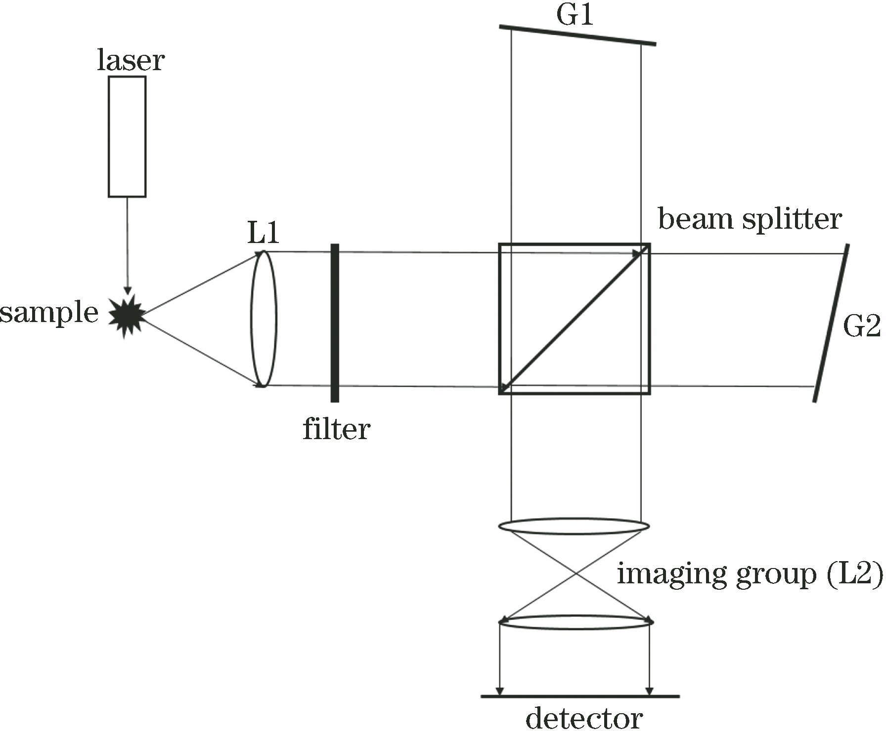
Fig. 1. Optical structure of spatial heterodyne Raman spectrometer
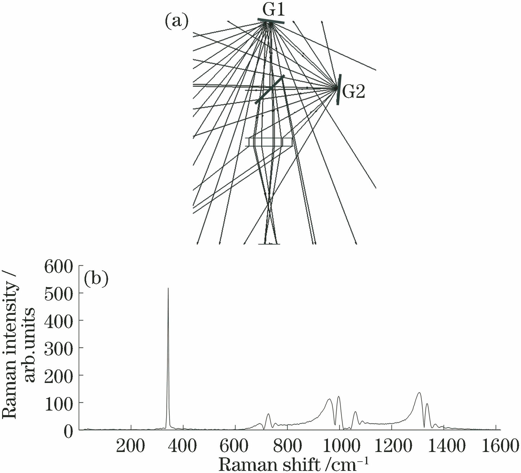
Fig. 2. Angular distribution and Raman spectrum. (a) Angular distribution for each diffraction order; (b) Raman spectrum of monochromatic light under multistage diffraction
Fig. 3. Multiple-wavelength noise superposition. (a) Signal noise of 1120 nm and 1130 nm; (b) signal noise of 1110 nm, 1120 nm, 1130 nm, and 1140 nm
Fig. 4. Distribution of stray light sources
Fig. 5. Partial light path in 0° FOV
Fig. 6. Position of G2 stop
Fig. 7. Schematic of light trap
Fig. 8. Position of light trap for compensating light leakage
Fig. 9. Positions of light traps and baffles
Fig. 10. Light path after stray light control
Fig. 11. Raman spectra before and after stray light control in 0° FOV. (a) Before control; (b) after control
Fig. 12. Spectra in different FOV ranges. (a) FOV of ±1.3°; (b) FOV of ±2.5°
Fig. 13. Schematic of field stop
Fig. 14. Spectra in multiple FOVs after control. (a) FOV of ±1.3°; (b) FOV of ±2.5°
Fig. 15. Structural diagram of system
Fig. 16. Interference fringes
|
Table 1. Parameters of SHRS system
|
Table 2. Illuminance distribution for each diffraction order

Set citation alerts for the article
Please enter your email address
© Copyright 2018-2021 | Chinese Laser Press. All Rights Reserved 沪ICP备15018463号-20