• Photonics Research
  • Vol. 10, Issue 11, 2642 (2022)
Zhimin Jing1, Peihang Li1, Cuiping Ma1, Jiaying Wang1, Roberto Caputo2, Alexander O. Govorov3, Arup Neogi1、6、*, Hongxing Xu4, and Zhiming Wang1、5、7、*
Author Affiliations
  • 1Institute of Fundamental and Frontier Sciences, University of Electronic Science and Technology of China, Chengdu 610054, China
  • 2Physics Department, University of Calabria, Rende I-87036, Italy
  • 3Department of Physics and Astronomy and Nanoscale and Quantum Phenomena Institute, Ohio University, Athens, Ohio 45701, USA
  • 4School of Physics and Technology, Center for Nanoscience and Nanotechnology, Wuhan University, Wuhan 430072, China
  • 5Institute for Advanced Study, Chengdu University, Chengdu 610106, China
  • 6e-mail:
  • 7e-mail:
  • show less
    DOI: 10.1364/PRJ.472087 Cite this Article Set citation alerts
    Zhimin Jing, Peihang Li, Cuiping Ma, Jiaying Wang, Roberto Caputo, Alexander O. Govorov, Arup Neogi, Hongxing Xu, Zhiming Wang. Active spatial control of photothermal heating and thermo-actuated convective flow by engineering a plasmonic metasurface with heterodimer lattices[J]. Photonics Research, 2022, 10(11): 2642 Copy Citation Text show less
    (a) Schematic of metal disk heterodimer (MDH) arrays consisting of a square array of MDH deposited onto a glass substrate. The environment of the MDH is index-matched with the substrate using solution (n=1.46). (b), (c) Schematic of the unit cell of the periodic array with d1=80 nm, d2=120 nm, g=40 nm, P=450 nm, and h=30 nm, where d is the diameter of the metal disk, 1 and 2 correspond to the two disks of MDH, g is the gap between disk 1 and disk 2, P is the period of the array, and h is the height of the disk. The steam bubbles presented here are just to illustrate the fluid vividly; they have nothing to do with boiling the fluid.
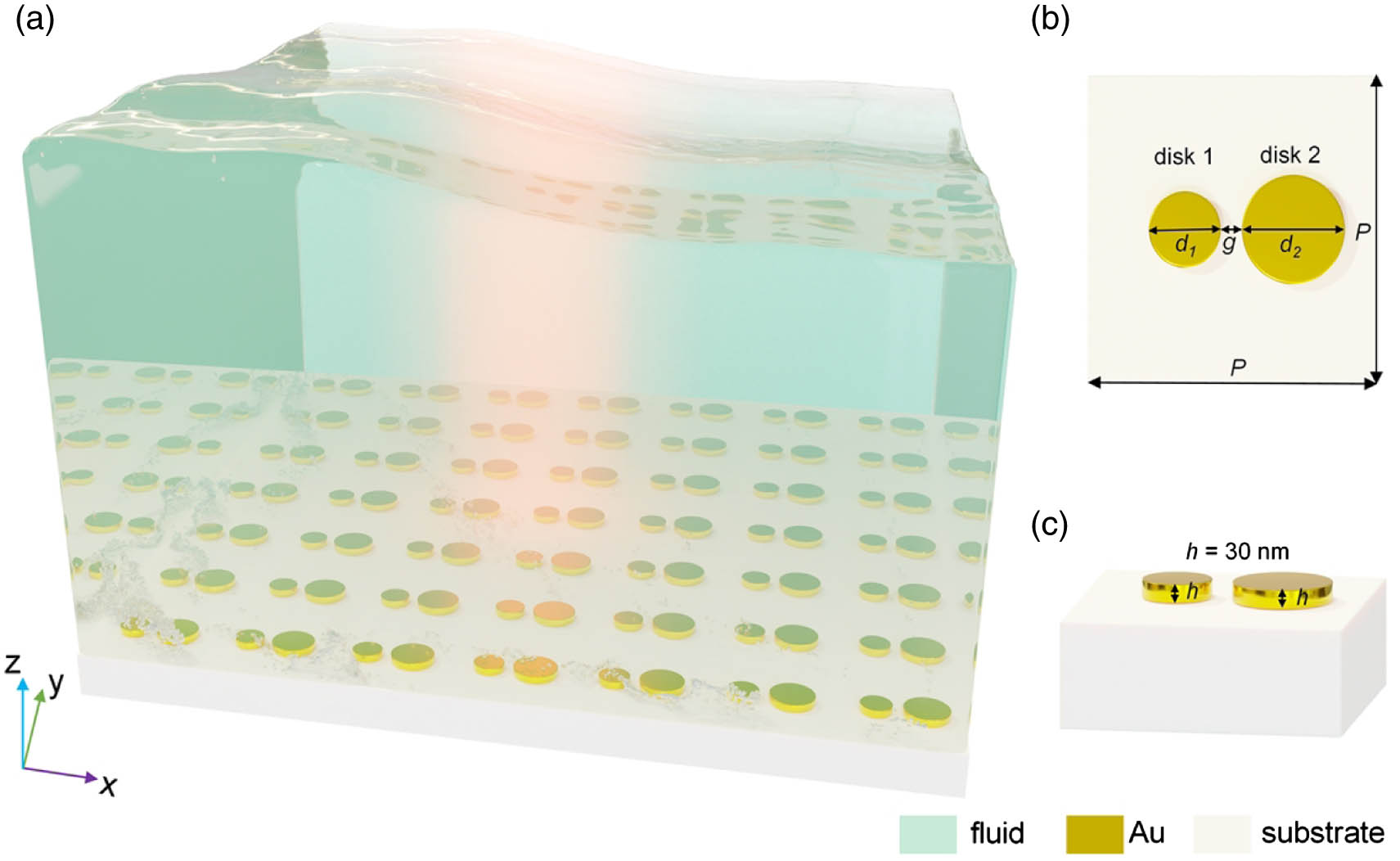
    Fig. 1. (a) Schematic of metal disk heterodimer (MDH) arrays consisting of a square array of MDH deposited onto a glass substrate. The environment of the MDH is index-matched with the substrate using solution (n=1.46). (b), (c) Schematic of the unit cell of the periodic array with d1=80  nm, d2=120  nm, g=40  nm, P=450  nm, and h=30  nm, where d is the diameter of the metal disk, 1 and 2 correspond to the two disks of MDH, g is the gap between disk 1 and disk 2, P is the period of the array, and h is the height of the disk. The steam bubbles presented here are just to illustrate the fluid vividly; they have nothing to do with boiling the fluid.
    Optical properties of plasmonic metasurface. (a) Extinction spectra of MDH arrays for x- and y-polarized incidence conditions. Inset: unit cell of MDH arrays. (b) Extinction spectra of homodimer 1 and homodimer 2 arrays for y-polarized incidence conditions. Inset: unit cells of homodimer 1 and 2 arrays. (c)–(h) Electric field distributions of MDH at the two resonant wavelengths of ∼679 nm and ∼775 nm under y polarization (c)–(f) and ∼786 nm under x-polarization (g), (h). (i) Schematic plasmon hybridization of MDH.
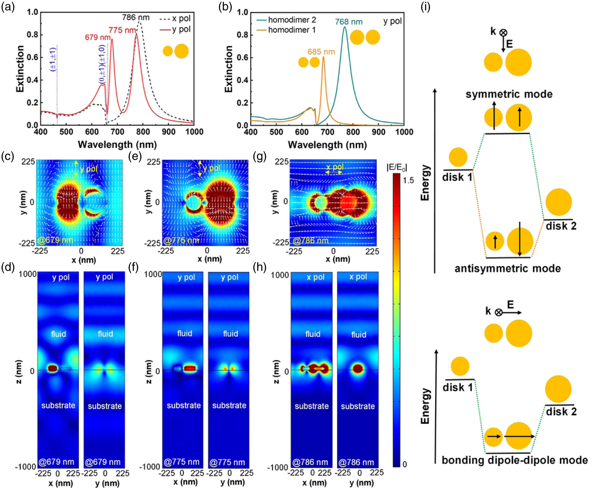
    Fig. 2. Optical properties of plasmonic metasurface. (a) Extinction spectra of MDH arrays for x- and y-polarized incidence conditions. Inset: unit cell of MDH arrays. (b) Extinction spectra of homodimer 1 and homodimer 2 arrays for y-polarized incidence conditions. Inset: unit cells of homodimer 1 and 2 arrays. (c)–(h) Electric field distributions of MDH at the two resonant wavelengths of 679  nm and 775  nm under y polarization (c)–(f) and 786  nm under x-polarization (g), (h). (i) Schematic plasmon hybridization of MDH.
    Controlled photothermal heating and thermo-actuated convective flow of MDH under different incident wavelengths and polarizations at the nanoscale. (a)–(f) Photoinduced control of temperature and thermally induced convection distributions in MDH. (g) Velocity map of the fluid flow along the x direction (y=0 nm and z=30 nm). Three different measuring points P1(0,0,30), P2(−200,0,30), and P3(200,0,30) are marked in green solid circle, magenta solid triangle, and turquoise solid square, respectively. All data are given at the time t=10 ns for the incident light flux of 104 W/cm2.
    Fig. 3. Controlled photothermal heating and thermo-actuated convective flow of MDH under different incident wavelengths and polarizations at the nanoscale. (a)–(f) Photoinduced control of temperature and thermally induced convection distributions in MDH. (g) Velocity map of the fluid flow along the x direction (y=0  nm and z=30  nm). Three different measuring points P1(0,0,30), P2(200,0,30), and P3(200,0,30) are marked in green solid circle, magenta solid triangle, and turquoise solid square, respectively. All data are given at the time t=10  ns for the incident light flux of 104  W/cm2.
    Heat generation of MDH arrays. (a) Total absorbed power of MDH arrays under different polarizations as a function of wavelength. Percentage contribution of heat generation in disks 1 and 2 to the total heat generation of MDH arrays under y-polarized illumination (b) and x-polarized illumination (c). (d) Heat generation at wavelengths under different polarizations.
    Fig. 4. Heat generation of MDH arrays. (a) Total absorbed power of MDH arrays under different polarizations as a function of wavelength. Percentage contribution of heat generation in disks 1 and 2 to the total heat generation of MDH arrays under y-polarized illumination (b) and x-polarized illumination (c). (d) Heat generation at wavelengths under different polarizations.
    Wavelength-dependent spatial axial temperature and velocity distributions in MDH. Schematic of the (a) x−y plane and (b) x−z plane marked with three lines of MDH. Temperature distributions of MDH under different incident wavelengths along the (c) x direction and (d) y direction. Temperature distributions of MDH along three different z directions (lines 1, 2, and 3) at (e) 679 nm and (f) 775 nm. Velocity component distributions of MDH under different incident wavelengths along the (g) x direction (y=0 nm, z=458 nm), (h) y direction (x=0 nm, z=458 nm), and (i) z direction (line 2). All data are acquired when the system reaches a steady state. The maximum temperatures along lines 1, 2, and 3 are 51.9°C, 45.5°C, and 41.1°C at 679 nm incident wave, and the maximum temperatures along lines 1, 2, and 3 are 39.4°C, 42.2°C, and 45.7°C at 775 nm incident wave, respectively.
    Fig. 5. Wavelength-dependent spatial axial temperature and velocity distributions in MDH. Schematic of the (a) xy plane and (b) xz plane marked with three lines of MDH. Temperature distributions of MDH under different incident wavelengths along the (c) x direction and (d) y direction. Temperature distributions of MDH along three different z directions (lines 1, 2, and 3) at (e) 679 nm and (f) 775 nm. Velocity component distributions of MDH under different incident wavelengths along the (g) x direction (y=0  nm, z=458  nm), (h) y direction (x=0  nm, z=458  nm), and (i) z direction (line 2). All data are acquired when the system reaches a steady state. The maximum temperatures along lines 1, 2, and 3 are 51.9°C, 45.5°C, and 41.1°C at 679 nm incident wave, and the maximum temperatures along lines 1, 2, and 3 are 39.4°C, 42.2°C, and 45.7°C at 775 nm incident wave, respectively.
    Wavelength-dependent temporal temperature and velocity distributions in MDH. (a) Temperature of two disks as a function of time at 679 nm. (b) Temperature of two disks as a function of time at 775 nm. (c) Average temperature and velocity of the fluid as a function of time at 679 nm. (d) Average temperature and velocity of the fluid as a function of time at 775 nm.
    Fig. 6. Wavelength-dependent temporal temperature and velocity distributions in MDH. (a) Temperature of two disks as a function of time at 679 nm. (b) Temperature of two disks as a function of time at 775 nm. (c) Average temperature and velocity of the fluid as a function of time at 679 nm. (d) Average temperature and velocity of the fluid as a function of time at 775 nm.
    Flexibility of resonance wavelength, temperature, and velocity. (a) Extinction spectra plotted as a function of wavelengths and periods. (b) Ratio of the temperature difference and fluid velocity of resonance mode I to mode II as a function of periods. (c) Extinction spectra plotted as a function of wavelengths and gaps. (d) Ratio of the temperature difference and fluid velocity of resonance mode I to mode II as a function of gaps. (e) Extinction spectra plotted as a function of wavelengths and diameters of disk 1. (f) Ratio of the temperature difference and fluid velocity of resonance mode I to mode II as a function of d1. (g) Extinction spectra plotted as a function of wavelengths and diameters of disk 2. (h) Ratio of the temperature difference and fluid velocity of resonance mode I to mode II as a function of d2.
    Fig. 7. Flexibility of resonance wavelength, temperature, and velocity. (a) Extinction spectra plotted as a function of wavelengths and periods. (b) Ratio of the temperature difference and fluid velocity of resonance mode I to mode II as a function of periods. (c) Extinction spectra plotted as a function of wavelengths and gaps. (d) Ratio of the temperature difference and fluid velocity of resonance mode I to mode II as a function of gaps. (e) Extinction spectra plotted as a function of wavelengths and diameters of disk 1. (f) Ratio of the temperature difference and fluid velocity of resonance mode I to mode II as a function of d1. (g) Extinction spectra plotted as a function of wavelengths and diameters of disk 2. (h) Ratio of the temperature difference and fluid velocity of resonance mode I to mode II as a function of d2.
    x−z cross-sectional view of the model used in the simulation of the MDH.
    Fig. 8. xz cross-sectional view of the model used in the simulation of the MDH.
    Surface charge distributions of resonance modes for different illuminated polarizations. Surface charge distributions of MDH at (a) 679 nm and (b) 775 nm for y-polarized excitation case. (c) Surface charge distributions of MDH at 786 nm for x-polarized excitation case.
    Fig. 9. Surface charge distributions of resonance modes for different illuminated polarizations. Surface charge distributions of MDH at (a) 679 nm and (b) 775 nm for y-polarized excitation case. (c) Surface charge distributions of MDH at 786 nm for x-polarized excitation case.
    Wavelength-dependent spatial axial temperature and velocity distributions in MDH in the case of x-polarized incident wave. (a) Temperature distributions of MDH along the x direction (y=0 nm, z=0 nm). (b) Velocity component distributions of MDH along the x direction (y=0 nm, z=458 nm). (c) Temperature distributions of MDH along the y direction (x=0 nm, z=0 nm). (d) Velocity component distributions of MDH along the y direction (x=0 nm, z=458 nm). (e) Temperature distributions of MDH along different z directions (lines 1, 2, and 3). (f) Velocity component distributions of MDH along the z direction (line 2). Schematics of the x−y plane and x−z plane marked with three lines of MDH are shown in Figs. 5(a) and 5(b). The maximum temperatures along lines 1, 2, and 3 are 38.0°C, 39.6°C, and 42.0°C at 786 nm incident wave, respectively.
    Fig. 10. Wavelength-dependent spatial axial temperature and velocity distributions in MDH in the case of x-polarized incident wave. (a) Temperature distributions of MDH along the x direction (y=0  nm, z=0  nm). (b) Velocity component distributions of MDH along the x direction (y=0  nm, z=458  nm). (c) Temperature distributions of MDH along the y direction (x=0  nm, z=0  nm). (d) Velocity component distributions of MDH along the y direction (x=0  nm, z=458  nm). (e) Temperature distributions of MDH along different z directions (lines 1, 2, and 3). (f) Velocity component distributions of MDH along the z direction (line 2). Schematics of the xy plane and xz plane marked with three lines of MDH are shown in Figs. 5(a) and 5(b). The maximum temperatures along lines 1, 2, and 3 are 38.0°C, 39.6°C, and 42.0°C at 786 nm incident wave, respectively.
    Wavelength-dependent temporal temperature and velocity distributions in MDH in the case of x-polarized incident wave. (a) Temperature of two disks as a function of time under the incident wavelength of 786 nm. (b) Average temperature and velocity of fluid as a function of time under the incident wavelength of 786 nm.
    Fig. 11. Wavelength-dependent temporal temperature and velocity distributions in MDH in the case of x-polarized incident wave. (a) Temperature of two disks as a function of time under the incident wavelength of 786 nm. (b) Average temperature and velocity of fluid as a function of time under the incident wavelength of 786 nm.
    Extinction spectra of the MDH with different incident angles of α=0°, 2°, 4°, 6°, 8°, 10°. With the increase of α, mode II exhibits an obvious redshift, mode I gradually splits, and more new modes appear. It is conceivable that this phenomenon will inevitably lead to the flexibility of optical heating and thermal convection.
    Fig. 12. Extinction spectra of the MDH with different incident angles of α=0°, 2°, 4°, 6°, 8°, 10°. With the increase of α, mode II exhibits an obvious redshift, mode I gradually splits, and more new modes appear. It is conceivable that this phenomenon will inevitably lead to the flexibility of optical heating and thermal convection.
    Temperature and fluid convection patterns under different incident wavelengths and polarizations of 5×5 array of MDH. The data are given at different illumination times (t=10 ns, 1000 ns).
    Fig. 13. Temperature and fluid convection patterns under different incident wavelengths and polarizations of 5×5 array of MDH. The data are given at different illumination times (t=10  ns, 1000 ns).
    Zhimin Jing, Peihang Li, Cuiping Ma, Jiaying Wang, Roberto Caputo, Alexander O. Govorov, Arup Neogi, Hongxing Xu, Zhiming Wang. Active spatial control of photothermal heating and thermo-actuated convective flow by engineering a plasmonic metasurface with heterodimer lattices[J]. Photonics Research, 2022, 10(11): 2642
    Download Citation