
Shuxin Wang, Tingting Lang, Guangyi Song, Jianjun He. SiON-Based Cyclic Arrayed Waveguide Grating Routers with Improved Loss Uniformity[J]. Acta Optica Sinica, 2019, 39(11): 1123001
- Acta Optica Sinica
- Vol. 39, Issue 11, 1123001 (2019)
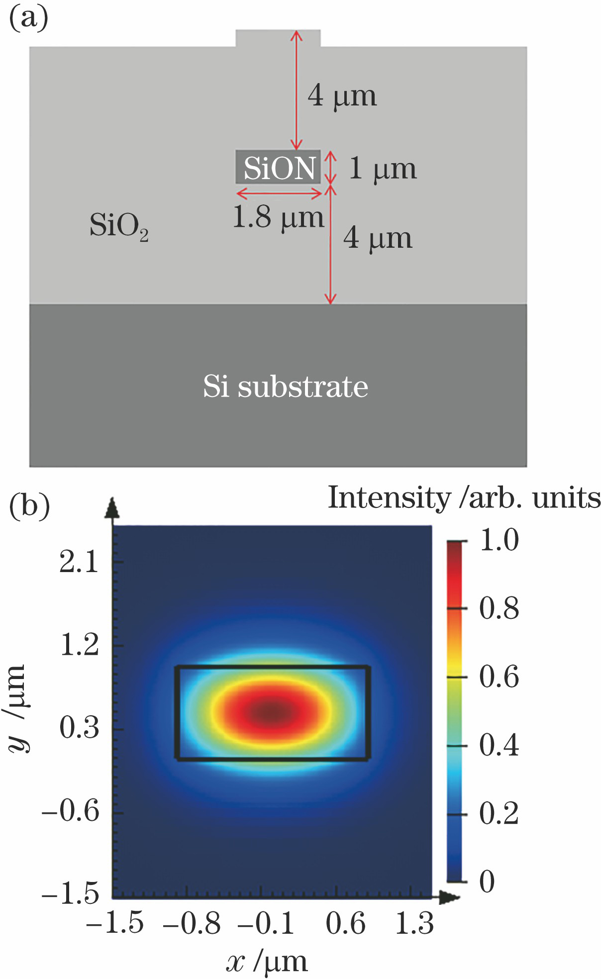
Fig. 1. Designed waveguide. (a) Cross section; (b) simulated field distribution of TM polarization
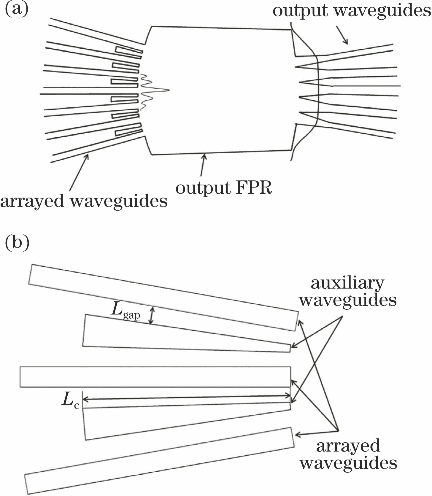
Fig. 2. Desired far field distribution of the designed and the detailed structure of the auxiliary waveguides. (a) Desired waveguide array with auxiliary waveguides (expected sinc field distribution in the output of a single array waveguide and the flat-topped field distribution in the output image plane are indicated in the figure); (b) detailed structure of auxiliary waveguides
Fig. 3. Field distribution with the conventional design and optimal design at the image plane
Fig. 4. Microscope pictures of the fabricated AWGR. (a) AWGR with auxiliary waveguides; (b) AWGR without auxiliary waveguides
Fig. 5. Pictures of the fabricated waveguides. (a) Microscope picture of the connection area of the waveguide array with auxiliary waveguides and the output FPR; (b) SEM image of the SiON waveguide cross section
Fig. 6. Transmission spectra of the designed 7×7 AWGR with auxiliary waveguides. (a) Edge input channel; (b) central input channel
Fig. 7. Transmission spectra of the conventional 7×7 AWGR. (a) Edge input channel; (b) central input channel
Fig. 8. Insertion loss for all output channels of the two 7×7 AWGRs. (a) Edge input channel; (b) central input channel
Fig. 9. Transmission spectra of each input channel when light is input backward
Fig. 10. Insertion loss comparation when light is input forward and backward
|
Table 1. Parameters of the 7×7 AWGR
|
Table 2. Summary of the research on AWGRs

Set citation alerts for the article
Please enter your email address
© Copyright 2018-2021 | Chinese Laser Press. All Rights Reserved 沪ICP备15018463号-20