
Jia-Lu Zhu, Ren-Chao Jin, Li-Li Tang, Zheng-Gao Dong, Jia-Qi Li, Jin Wang, "Multidimensional trapping by dual-focusing cylindrical vector beams with all-silicon metalens," Photonics Res. 10, 1162 (2022)
- Photonics Research
- Vol. 10, Issue 5, 1162 (2022)
Abstract
1. INTRODUCTION
Cylindrical vector beams (CVBs) with axially symmetric polarizations also called first-order vector beams [1] are generally classified into radially polarized vector beams (RPVBs), azimuthally polarized vector beams (APVBs), and hybridly polarized vector beams [2,3]. On account of the characteristic of inhomogeneous polarization, CVBs can be applied to multifarious fields, such as 3D polarization control [4], optical trapping [5,6], microscopic imaging [7–10], metrology [11–13], and optical communication [14–18]. Moreover, CVBs of the terahertz band, a wave band with plentiful applications of cutting-edge technology [19,20], can also be used for electron acceleration [21] and improve the coupling efficiency of the waveguide [22]. Radially and azimuthally polarized beams as two typical CVBs have been paid more and more attention. RPVBs have significant longitudinally polarized spots when tightly focused [23], making it more efficient for axial optical manipulation of nanoparticles as compared with linearly polarized light [24]. In addition, RPVBs can break the diffraction limit [25], promising for high-resolution lithography and optical sensing [26]. On the other hand, it was demonstrated that APVBs had stronger ability in transverse trapping, in contrast to RPVBs [27–29]. Several technical methods for generating such CVBs were developed, for example, retardation phase plates [23,30,31], subwavelength space-variant metallic gratings [32], and dielectric gratings [33]. Nevertheless, these methods are often plagued by problems, such as bulky size and fabrication difficulty.
Metamaterials as a kind of artificial materials different from natural materials provide an innovative method of optical manipulation [34,35]. Metasurfaces, two-dimensional forms of metamaterials, have also been widely applied in various aspects, such as ultrathin polarizer [36–38], metalens [39,40], and holographic imaging [41,42] for their superior manipulations of amplitude, polarization, and phase on the subwavelength scale. Moreover, emerging all-dielectric metasurfaces can solve the problem of ohmic losses in plasmonic metasurfaces [39,40,43–45]. Therefore, metasurfaces are promising for highly-compact low-loss CVB nanodevices, and, in fact, there have been works on CVB generation [46,47] or focusing [48,49] by metasurfaces. However, there are few works on simultaneously generating RPVBs and APVBs, meanwhile focusing them in multidimensional positions, although recently, the hybrid dual-focusing effect has been demonstrated (i.e., one focusing is a CVB spot, whereas the other is a homogeneously polarized scalar-beam spot). Recently, there have been some works on multifocus metalens, but the vast majority of them concentrated on multifocusing of the phase-vortex beam with a helical wavefront, which is different from our vector beams with inhomogeneous polarization rather than phase [50,51]. In our previous work, we have already experimentally demonstrated multidimensional and multifunctional metalens based on the photonic spin Hall effect [52] as well as spin-dependent dual-wavelength multiplexing metalens [53]. In this paper, we use the design criterion, so-called spin-decoupled phase control previously adopted for the generation of a single CVB [54] to realize multidimensional simultaneous focusing of RPVBs and APVBs based on an all-silicon metalens, indicating that this design criterion is sophisticated for complex vector-light metalenses. Attributed to the anisotropic bar structure, both polarization and wavefront of transmitted light are controlled by the combined modulation of geometric and dynamic phases. The polarization dependence of the vector beam on incident light determines that the focal positions of both vector beams can be easily exchanged by switching the polarization of incident light, which provides much convenience for practical optical operations. Optical forces of the focused RPVBs and APVBs on a glass sphere were calculated, confirming the contribution of the focusing RPVB (or APVB) to longitudinal (or transverse) optical force. The advantage of this paper for multidimensional simultaneous focusing of RPVBs and APVBs is that multichannel simultaneous manipulation (transverse and longitudinal manipulations) in a multidimensional position can be realized, that is, two kinds of CVBs can be focused or two different types of manipulation (the transverse and longitudinal trappings) can be realized at the same time. Meanwhile, these two kinds of manipulation will not be confined to the same point in space, which is different from a single focused beam of RPVB or APVB that can perform only one manipulation (transverse manipulation or longitudinal manipulation) at a time, and all of these controls will be stuck at the same point in space. In this way, the system of a multidimensional polarization-dependent dual-focusing CVB will enrich the optical control effect [55–57], and more possibilities will be brought to the integration of optical systems.
2. PRINCIPLE
Figure 1(a) shows the elementary bar on a silicon substrate, a simple anisotropic structure usually adopted in literature [36,39,43–45,54]. The silicon bar has a height
Sign up for Photonics Research TOC. Get the latest issue of Photonics Research delivered right to you!Sign up now
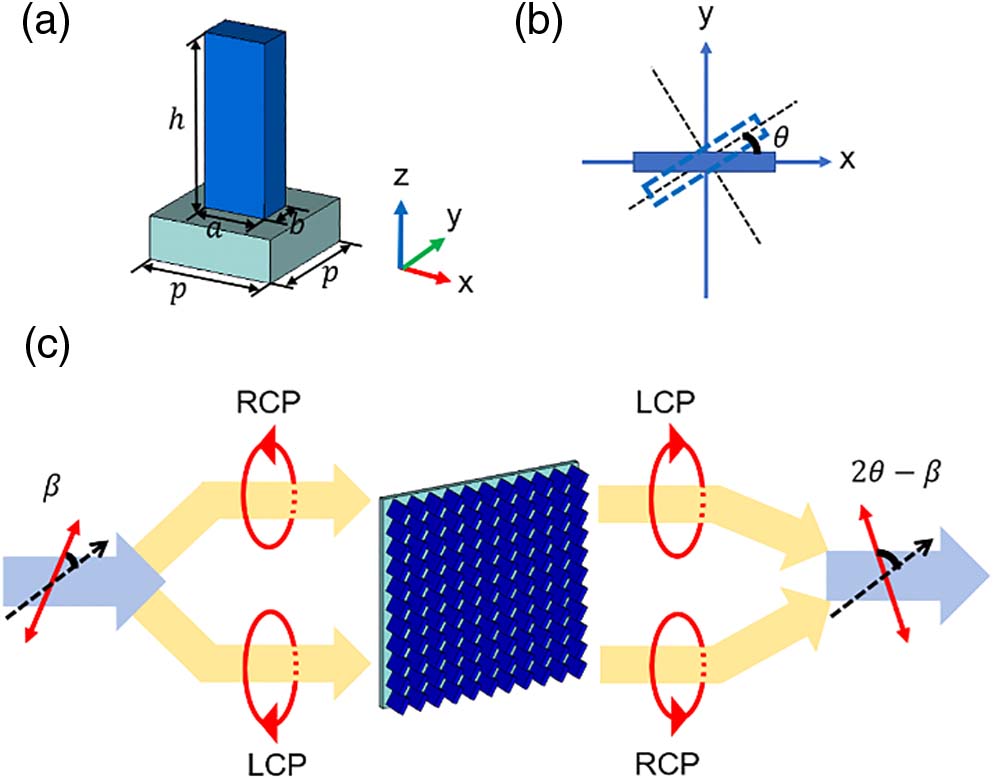
Figure 1.Schematic of the anisotropic elementary unit and the working principle for the CVB converter. (a) The all-silicon unit configuration consisting of the bar and substrate. (b) The rotation angle
In this paper, we use the spin-decoupled phase control method [54] based on dynamic and geometric phases to generate multidimensional polarization-dependent dual-focusing CVBs. Excitation light is incident normally from the substrate end of the structure. The superposition of the dynamic and geometric phases is used to represent the phase shift due to the interaction between the structure and the incident light,
For RCP incident component
Equation (5) indicates that the transmitted light is linearly polarized along a direction angle (
In order to achieve a transmission beam with radial polarization (
To achieve azimuthally polarized transmission, i.e.,
It is noted that for the respective bar with determined rotation direction
In addition, as the dynamic phase,
3. RESULTS AND DISCUSSION
A. Design of Elementary Unit
Before assembling metalens with the corresponding properties, elementary bars with suitable sizes are optimized not only to satisfy the half-wave plate condition (phase difference
![]()
Figure 2.Simulation of transmission amplitude (
In order to verify whether these eight bars meet the conditions of half-wave plates and explore the working bandwidth of the bars, amplitudes (
![]()
Figure 3.Simulated amplitude (
Next, with the amplitude and phase databases for eight bars, we design the arrangement of elements based on the aforesaid design principle, which is feasible to realize multidimensional dual-focusing CVB.
B. Transverse Dual-Focusing Terahertz Vector Beams
Figure 4 illustrates the schematic of a transverse dual-focusing CVB system. For simplicity, the incident light is assumed to be
![]()
Figure 4.Schematic of the transverse dual-focusing CVB system. The inset on the right illustrates the specific arrangement of metasurface elements.
Figure 5 shows the finite-difference time-domain simulation results of the transverse dual-focusing CVB system. It can be clearly found from Fig. 5(a) that there are two CVB focal spots separated perpendicular to the propagation direction of incident light, namely, the transverse
![]()
Figure 5.Simulation results of the transverse dual-focusing CVB system under the incidence of
C. Longitudinal Dual-Focusing Terahertz Vector Beams
The longitudinal dual-focusing CVB system is illustrated in Fig. 6. Similarly,
![]()
Figure 6.Schematic of the longitudinal dual-focusing CVB system. The top inset illustrates the arrangement of the bar elements.
Figures 7(a) and 7(b) illustrate the
![]()
Figure 7.Simulation results of the longitudinal dual-focusing CVB system under the incidence of
1. Polarization Dependence
As can be found from the principle described in Section 2, the polarization distribution at the focal position can be switched from radial/azimuthal polarization to azimuthal/radial polarization by converting the polarization direction of the incident light orthogonally. Taking the longitudinal dual-focusing metalens as an example, converting the incident light from
Figures 8(a) and 8(b) show simulation results to confirm the polarization dependence of our longitudinal dual-focusing CVB metalens. Obviously, the original focal spot with radial/azimuthal polarization does interconvert into a focal spot with orthogonal azimuthal/radial polarization. Figures 8(c)–8(h) can verify the azimuthal and radial polarization characteristics at spots
![]()
Figure 8.Simulation results of the longitudinal polarization-dependent dual-focusing CVB system under the incidence of
2. Calculation of Optical Force
Taking the longitudinal dual-focusing CVB system as an example, based on the ray tracing method [24,27,58], optical forces, corresponding to the tight-focusing fields of APVB and RPVB, were calculated to investigate the characteristics of tiny particle manipulation by such dual-focusing CVBs, which should contribute to multidimensional vector-light tweezers.
For simplicity, we consider the optical forces stressed by the focused RPVB (or APVB) at focal point
![]()
Figure 9.Calculation results of the optical force. (a) Schematic of the longitudinal dual-focusing CVB metalens and the glass sphere which is subjected to the optical force. (b) Calculated longitudinal optical force
Figure 9(b) illustrates the calculated longitudinal optical force
4. CONCLUSION
In this paper, the multidimensional dual-focusing CVB metalens with an all-silicon configuration was proposed under the design principle of spin-decoupled phase control from which a pair of focused vector beams with radial and azimuthal polarizations can be generated in the transverse as well as the longitudinal directions. Furthermore, we calculated the optical forces of such APVB and RPVB focusing spots exerted on a glass sphere and, consequently, revealed the transverse and longitudinal trapping characteristics, attributed to the hollow singularity of APVB and to the convergence singularity of RPVB in the case of focusing, respectively. Moreover, the polarization distributions of the dual-focusing CVB metalens can be interchanged by simply switching the polarization direction of incident light, providing much convenience in multidimensional multichannel optical trapping by focused vector beams. What needs to be pointed out is that our paper only considered forces of APVB and RPVB acting on the glass sphere and numerically proved the transverse and longitudinal trapping forces of these two focused vector beams on the glass sphere. Further research is needed to trap the sphere experimentally. For example, for the focused RPVB in this paper, its longitudinal trapping force is not large enough to fight against other forces, if any, such as the gravity force of the glass sphere or air resistance, and considering the difficulty of providing incident power strong enough in the experiment if we really want to experimentally achieve the longitudinal trapping of the sphere against its gravity with the focused RPVB, Some effort, such as adjusting the operating band to the visible/near-infrared band is necessary to improve the trapping force. Lastly, it is noted that the design strategy, so-called spin-decoupled phase control, can be extended to high-order vector beams, promising for the high integration of the optical system with potential applications in polarization-dependent optical communication, information encryption, imaging, and so on.
References
[1] E. Otte, C. Denz. Optical trapping gets structure: structured light for advanced optical manipulation. Appl. Phys. Rev., 7, 041308(2020).
[2] J. Li, S. Chen, H. Yang, J. Li, P. Yu, H. Cheng, C. Gu, H.-T. Chen, J. Tian. Simultaneous control of light polarization and phase distributions using plasmonic metasurfaces. Adv. Funct. Mater., 25, 704-710(2015).
[3] Q. W. Zhan. Cylindrical vector beams: from mathematical concepts to applications. Adv. Opt. Photon., 1, 1-57(2009).
[4] X. Li, T. H. Lan, C. H. Tien, M. Gu. Three-dimensional orientation-unlimited polarization encryption by a single optically configured vectorial beam. Nat. Commun., 3, 998(2012).
[5] N. Bhebhe, C. Rosales-Guzmán, A. Forbes. Classical and quantum analysis of propagation invariant vector flat-top beams. Appl. Opt., 57, 5451-5458(2018).
[6] Y. Zhao, Q. Zhan, Y. Zhang, Y.-P. Li. Creation of a three-dimensional optical chain for controllable particle delivery. Opt. Lett., 30, 848-850(2005).
[7] R. Chen, K. Agarwal, C. J. R. Sheppard, X. D. Chen. Imaging using cylindrical vector beams in a high-numerical-aperture microscopy system. Opt. Lett., 38, 3111-3114(2013).
[8] M. Yoshid, Y. Kozawa, S. Sato. Subtraction imaging by the combination of higher-order vector beams for enhanced spatial resolution. Opt. Lett., 44, 883-886(2019).
[9] S. Segawa, Y. Kozawa, S. Sato. Resolution enhancement of confocal microscopy by subtraction method with vector beams. Opt. Lett., 39, 3118-3121(2014).
[10] S. Segawa, Y. Kozawa, S. Sato. Demonstration of subtraction imaging in confocal microscopy with vector beams. Opt. Lett., 39, 4529-4532(2014).
[11] F. Töppel, A. Aiello, C. Marquardt, E. Giacobino, G. Leuchs. Classical entanglement in polarization metrology. New J. Phys., 16, 073019(2014).
[12] S. Berg-Johansen, F. Töppel, B. Stiller, P. Banzer, M. Ornigotti, E. Giacobino, G. Leuchs, A. Aiello, C. Marquardt. Classically entangled optical beams for high-speed kinematic sensing. Optica, 2, 864-868(2015).
[13] M. Neugebauer, P. Wozniak, A. Bag, G. Leuchs, P. Banzer. Polarization-controlled directional scattering for nanoscopic position sensing. Nat. Commun., 7, 11286(2016).
[14] B. Ndagano, I. Nape, M. A. Cox, C. Rosales-Guzmán, A. Forbes. Creation and detection of vector vortex modes for classical and quantum communication. J. Lightwave Technol., 36, 292-301(2018).
[15] G. Milione, T. A. Nguyen, J. Leach, D. A. Nolan, R. R. Alfano. Using the nonseparability of vector beams to encode information for optical communication. Opt. Lett., 40, 4887-4890(2015).
[16] V. D’Ambrosio, G. Carvacho, F. Graffitti, C. Vitelli, B. Piccirillo, L. Marrucci, F. Sciarrino. Entangled vector vortex beams. Phys. Rev. A, 94, 030304(2016).
[17] J. Liu, S. M. Li, L. Zhu, A. D. Wang, S. Chen, C. Klitis, C. Du, Q. Mo, M. Sorel, S. Y. Yu, X. L. Cai, J. Wang. Direct fiber vector eigenmode multiplexing transmission seeded by integrated optical vortex emitters. Light Sci. Appl., 7, 17148(2018).
[18] D. Chen, S.-H. Zhao, L. Shi, Y. Liu. Measurement-device-independent quantum key distribution with pairs of vector vortex beams. Phys. Rev. A, 93, 032320(2016).
[19] M. Tonouchi. Cutting-edge terahertz technology. Nat. Photonics, 1, 97-105(2007).
[20] W. He, M. Tong, Z. Xu, Y. Hu, X. A. Cheng, T. Jiang. Ultrafast all-optical terahertz modulation based on an inverse-designed metasurface. Photon. Res., 9, 1099-1108(2021).
[21] E. A. Nanni, W. R. Huang, K.-H. Hong, K. Ravi, A. Fallahi, G. Moriena, R. D. Miller, F. X. Kärtner. Terahertz-driven linear electron acceleration. Nat. Commun., 6, 8486(2015).
[22] J. A. Deibel, K. Wang, M. D. Escarra, D. M. Mittleman. Enhanced coupling of terahertz radiation to cylindrical wire waveguides. Opt. Express, 14, 279-290(2006).
[23] S. Quabis, R. Dorn, M. Eberler, O. Glöckl, G. Leuchs. Focusing light to a tighter spot. Opt. Commun., 179, 1-7(2000).
[24] M. Michihata, T. Hayashi, Y. Takaya. Measurement of axial and transverse trapping stiffness of optical tweezers in air using a radially polarized beam. Appl. Opt., 48, 6143-6151(2009).
[25] R. Zuo, W. Liu, H. Cheng, S. Chen, J. Tian. Breaking the diffraction limit with radially polarized light based on dielectric metalenses. Adv. Opt. Mater., 6, 1800795(2018).
[26] F. Yue, D. Wen, J. Xin, B. D. Gerardot, J. Li, X. Chen. Vector vortex beam generation with a single plasmonic metasurface. ACS Photon., 3, 1558-1563(2016).
[27] Y. Kozawa, S. Sato. Optical trapping of micrometer-sized dielectric particles by cylindrical vector beams. Opt. Express, 18, 10828-10833(2010).
[28] S. E. Skelton, M. Sergides, R. Saija, M. A. Iatì, O. M. Maragó, P. H. Jones. Trapping volume control in optical tweezers using cylindrical vector beams. Opt. Lett., 38, 28-30(2013).
[29] M. G. Donato, S. Vasi, R. Sayed, P. H. Jones, F. Bonaccorso, A. C. Ferrari, P. G. Gucciardi, O. M. Maragó. Optical trapping of nanotubes with cylindrical vector beams. Opt. Lett., 37, 3381-3383(2012).
[30] S. Quabis, R. Dorn, G. Leuchs. Generation of a radially polarized doughnut mode of high quality. Appl. Phys. B, 81, 597-600(2005).
[31] G. Machavariani, Y. Lumer, I. Moshe, A. Meir, S. Jackel. Efficient extracavity generation of radially and azimuthally polarized beams. Opt. Lett., 32, 1468-1470(2007).
[32] Z. Bomzon, V. Kleiner, E. Hasman. Pancharatnam–Berry phase in space-variant polarization-state manipulations with subwavelength gratings. Opt. Lett., 26, 1424-1426(2001).
[33] Z. Bomzon, G. Biener, V. Kleiner, E. Hasman. Radially and azimuthally polarized beams generated by space-variant dielectric subwavelength gratings. Opt. Lett., 27, 285-287(2002).
[34] Y. Liu, X. Zhang. Metamaterials: a new frontier of science and technology. Chem. Soc. Rev., 40, 2494-2507(2011).
[35] D. Lee, S. So, G. Hu, M. Kim, T. Badloe, H. Cho, J. Kim, H. Kim, C. Qiu, J. Rho. Hyperbolic metamaterials: fusing artificial structures to natural 2D materials. eLight, 2, 1(2022).
[36] Z. C. Liu, Z. C. Li, Z. Liu, H. Cheng, W. W. Liu, C. C. Tang, C. Z. Gu, J. J. Li, H. T. Chen, S. Q. Chen, J. G. Tian. Single-layer plasmonic metasurface half-wave plates with wavelength-independent polarization conversion angle. ACS Photon., 4, 2061-2069(2017).
[37] B. Bai, Y. Svirko, J. Turunen, T. Vallius. Optical activity in planar chiral metamaterials: theoretical study. Phys. Rev. A, 76, 023811(2007).
[38] A. Drezet, C. Genet, J.-Y. Laluet, T. W. Ebbesen. Optical chirality without optical activity: how surface plasmons give a twist to light. Opt. Express, 16, 12559-12570(2008).
[39] M. Khorasaninejad, W. T. Chen, R. C. Devlin, J. Oh, A. Y. Zhu, F. Capasso. Metalenses at visible wavelengths: diffraction-limited focusing and subwavelength resolution imaging. Science, 352, 1190-1194(2016).
[40] E. Arbabi, A. Arbabi, S. M. Kamali, Y. Horie, A. Faraon. Multiwavelength polarization-insensitive lenses based on dielectric metasurfaces with meta-molecules. Optica, 3, 628-633(2016).
[41] G. Zheng, H. Muehlenbernd, M. Kenney, G. Li, T. Zentgraf, S. Zhang. Metasurface holograms reaching 80% efficiency. Nat. Nanotechnol., 10, 308-312(2015).
[42] J. P. B. Mueller, N. A. Rubin, R. C. Devlin, B. Groever, F. Capasso. Metasurface polarization optics: independent phase control of arbitrary orthogonal states of polarization. Phys. Rev. Lett., 118, 113901(2017).
[43] T. Li, X. Xu, B. Fu, S. Wang, B. Li, Z. Wang, S. Zhu. Integrating the optical tweezers and spanner onto an individual single-layer metasurface. Photon. Res., 9, 1062-1068(2021).
[44] S. Gao, C. S. Park, S. S. Lee, D. Y. Choi. All-dielectric metasurface for simultaneously realizing polarization rotation and wavefront shaping for visible light. Nanoscale, 11, 4083-4090(2019).
[45] Y. Hu, X. Wang, X. Luo, X. Ou, L. Li, Y. Chen, Y. Ping, S. Wang, H. Duan. All-dielectric metasurfaces for polarization manipulation: principles and emerging applications. Nanophotonics, 9, 3755-3780(2020).
[46] D. Wang, T. Liu, Y. Zhou, X. Zheng, S. Sun, Q. He, L. Zhou. High-efficiency metadevices for bifunctional generations of vectorial optical fields. Nanophotonics, 10, 685-695(2020).
[47] W. Shu, Y. Liu, Y. Ke, X. Ling, Z. Liu, B. Huang, H. Luo, X. Yin. Propagation model for vector beams generated by metasurfaces. Opt. Express, 24, 21177-21189(2016).
[48] Y. Liu, Y. Ke, J. Zhou, Y. Liu, H. Luo, S. Wen, D. Fan. Generation of perfect vortex and vector beams based on Pancharatnam-Berry phase elements. Sci. Rep., 7, 44096(2017).
[49] F. Zhang, H. Yu, J. Fang, M. Zhang, S. Chen, J. Wang, A. He, J. Chen. Efficient generation and tight focusing of radially polarized beam from linearly polarized beam with all-dielectric metasurface. Opt. Express, 24, 6656-6664(2016).
[50] C. Zheng, J. Li, G. Wang, S. Wang, J. Li, H. Zhao, H. Zang, Y. Zhang, Y. Zhang, J. Yao. Fine manipulation of terahertz waves via all-silicon metasurfaces with an independent amplitude and phase. Nanoscale, 13, 5809-5816(2021).
[51] S. Gao, C. Park, C. Zhou, S. Lee, D. Choi. Twofold polarization-selective all-dielectric trifoci metalens for linearly polarized visible light. Adv. Opt. Mater., 7, 1900883(2019).
[52] R. Jin, L. Tang, J. Li, J. Wang, Q. Wang, Y. Liu, Z.-G. Dong. Experimental demonstration of multidimensional and multifunctional metalenses based on photonic spin Hall effect. ACS Photon., 7, 512-518(2020).
[53] L. Tang, R. Jin, Y. Cao, J. Li, J. Wang, Z. G. Dong. Spin-dependent dual-wavelength multiplexing metalens. Opt. Lett., 45, 5258-5261(2020).
[54] Y. Xu, H. Zhang, Q. Li, X. Zhang, Q. Xu, W. Zhang, C. Hu, X. Zhang, J. Han, W. Zhang. Generation of terahertz vector beams using dielectric metasurfaces via spin-decoupled phase control. Nanophotonics, 9, 3393-3402(2020).
[55] I. D. Stoev, B. Seelbinder, E. Erben, N. Maghelli, M. Kreysing. Highly sensitive force measurements in an optically generated, harmonic hydrodynamic trap. eLight, 1, 7(2021).
[56] H. Li, Y. Y. Cao, L. M. Zhou, X. H. Xu, T. T. Zhu, Y. Z. Shi, C. W. Qiu, W. Q. Ding. Optical pulling forces and their applications. Adv. Opt. Photon., 12, 288-366(2020).
[57] D. Gao, W. Ding, M. Nieto-Vesperinas, X. Ding, M. Rahman, T. Zhang, C. Lim, C. W. Qiu. Optical manipulation from the microscale to the nanoscale: fundamentals, advances and prospects. Light Sci. Appl., 6, e17039(2017).
[58] T. A. Nieminen, N. R. Heckenberg, H. Rubinsztein-Dunlop. Forces in optical tweezers with radially and azimuthally polarized trapping beams. Opt. Lett., 33, 122-124(2008).


Set citation alerts for the article
Please enter your email address

© Copyright 2018-2021 | Chinese Laser Press. All Rights Reserved 沪ICP备15018463号-20