
Jia CAI, Gaoxu HUANG, Xiaopan JIN, Chi WEI, Jiayi MAO, Yongsheng LI. In-situ Modification of Carbon Nanotubes with Metallic Bismuth Nanoparticles for Uniform Lithium Deposition[J]. Journal of Inorganic Materials, 2022, 37(12): 1337
- Journal of Inorganic Materials
- Vol. 37, Issue 12, 1337 (2022)
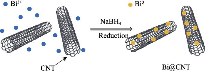
. Schematic diagram for the synthesis of Bi@CNT
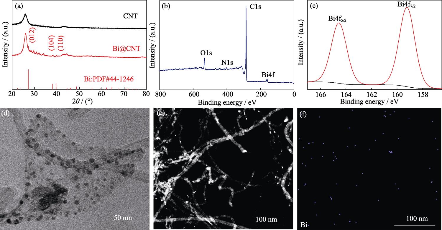
. Microstructure characterization of samples
. Coulombic efficiencies of Li|Cu cells based on Bi@CNT/Cu, CNT/Cu and Cu current collectors at (a) 1 mA·cm-2, 1 mAh·cm-2 and (b) 3 mA·cm-2, 1 mAh·cm-2; Capacity-voltage curves of Li|Cu cells based on (c) Bi@CNT/Cu, (d) CNT/Cu, and (e) Cu current collectors at 1 mA·cm-2, 1 mAh·cm-2
. SEM images of (a) Bi@CNT/Cu, (b) CNT/Cu, and (c) Cu current collectors in Li|Cu cells after 50 cycles; (d) First cyclic EIS plots of Li|Cu cells based on Bi@CNT/Cu, CNT/Cu and Cu current collectors, and voltage-time curves of symmetric cells based on Li@Bi@CNT/Cu, Li@CNT/Cu and Li@Cu anodes at (e) 1 mA·cm-2, 1 mAh·cm-2 and (f) 2 mA·cm-2, 1 mAh·cm-2
. (a) Cycling performances and (b) rate performances of LFP full cells based on Li@Bi@CNT/Cu, Li@CNT/Cu, and Li@Cu anodes, and (c-e) capacity-voltage profiles of LFP full cells based on (c) Li@Bi@CNT/Cu, (d) Li@CNT/Cu, and (e) Li@Cu anodes at 1C
| ||||||||||||||||||||||||||||||||||||||||||||||||||||||||||||||||||||||||||||||||||||||||||||||||||||||||||||||||||||||||||||
Table 1. Comparison of electrochemical properties of copper foils modified by different materials

Set citation alerts for the article
Please enter your email address
© Copyright 2018-2021 | Chinese Laser Press. All Rights Reserved 沪ICP备15018463号-20