
Shuwei Qiu, Jinwen Wang, Francesco Castellucci, Mingtao Cao, Shougang Zhang, Thomas W. Clark, Sonja Franke-Arnold, Hong Gao, Fuli Li, "Visualization of magnetic fields with cylindrical vector beams in a warm atomic vapor," Photonics Res. 9, 2325 (2021)
- Photonics Research
- Vol. 9, Issue 12, 2325 (2021)
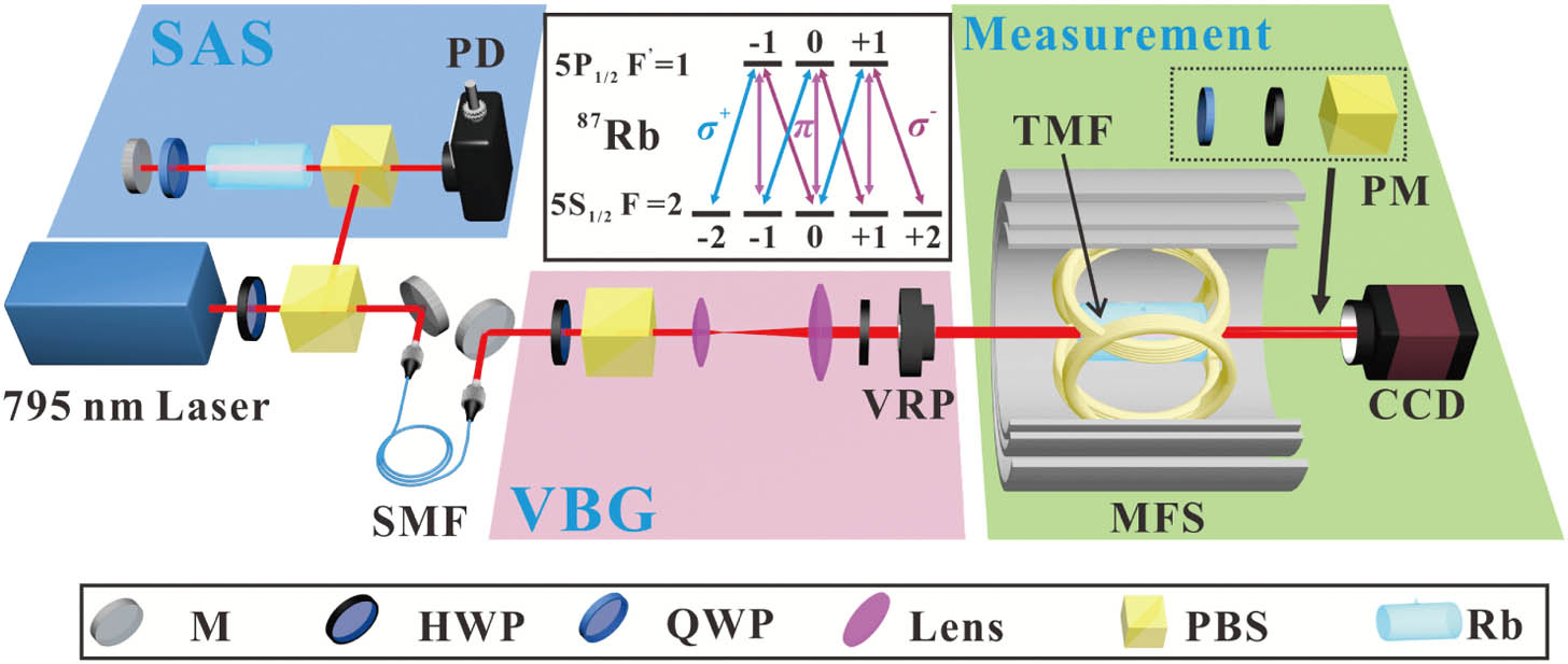
Fig. 1. Schematic of the experimental setup and atomic energy levels. M, mirror; HWP, half-wave plate; QWP, quarter-wave plate; L, lens; PBS, polarization beam splitter; PD, photodetector; SMF, single-mode fiber; VRP, vortex retarder plate; CCD, charge-coupled device camera; MFS, magnetic field shielding; PM, projection measurement; SAS, saturated absorption spectroscopy; VBG, vector beam generation.
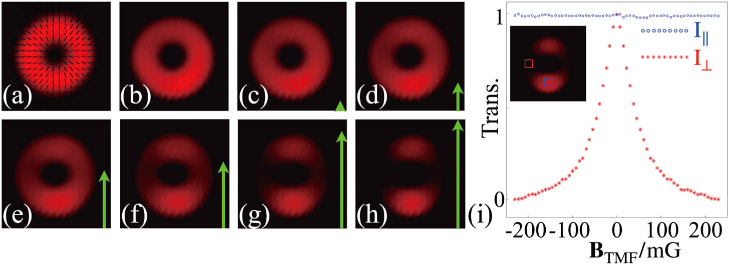
Fig. 2. Experimental results of the radially polarized beam in presence of TMF. (a) Intensity and polarization distribution without atoms. (b)–(h) Intensity distributions after passing through atoms under vertical TMF of varying strength: B TMF = 0 B TMF
Fig. 3. Experimental results of the radially polarized beam in presence of an LMF. (a)–(f) Intensity distributions after passing through the atom vapor under the varied LMF: B LMF = 0 B LMF
Fig. 4. Transmission profiles as functions of TMFs alignment. (a) and (b) Intensity and polarization distributions for vertical and diagonal TMF alignment. (c) Image axis of the transmission profile as a function of TMF alignment. Insets: examples of observed transmission profiles.
Fig. 5. Experimental results of the radially polarized beam in presence of the spatial magnetic field with fixed strength (| B | = 230 mG | B | = 0 mG θ = π / 6 , π / 4 , π / 3,5 π / 12 , π / 2 θ
Fig. 6. Polarization and intensity profiles for VBs with different polarization topological charges m = 1 m = 2 B TMF = 230 mG
Fig. 7. Excitation scheme for (a) the LMF and (d) the TMF. (b) Coherent dark state and (c) decoherent state induced by Zeeman splitting. Bare dark state (e) without and (f) with Zeeman splitting. In presence of the magnetic field, magnetic sublevels are shifted by an amount μ B g F m F B μ B g F B


Set citation alerts for the article
Please enter your email address

© Copyright 2018-2021 | Chinese Laser Press. All Rights Reserved 沪ICP备15018463号-20