
Shuwei Qiu, Jinwen Wang, Francesco Castellucci, Mingtao Cao, Shougang Zhang, Thomas W. Clark, Sonja Franke-Arnold, Hong Gao, Fuli Li, "Visualization of magnetic fields with cylindrical vector beams in a warm atomic vapor," Photonics Res. 9, 2325 (2021)
- Photonics Research
- Vol. 9, Issue 12, 2325 (2021)
Abstract
1. INTRODUCTION
Perhaps the most remarkable demonstrations of coherent interaction between atoms and photons are electromagnetically induced transparency (EIT), electromagnetically induced absorption (EIA), and coherent population trapping [1–4]. These processes can be interpreted as a consequence of quantum interference, i.e., they are based on the fact that an optical field can transform atomic states such that an atomic transition can be entirely suppressed and subsequent absorption eliminated. Quantum interference shows exceptional sensitivity to frequency shifts, including those induced by magnetic fields. This makes atomic ensembles an excellent tool for magnetometry, with potential application across research fields as diverse as biomedicine, seismology, defense, and general metrology [5,6].
Atomic magnetometers can now reach excellent sensitivities, comparable with and even surpassing those of superconducting quantum interference devices [7–9]. Since the first demonstration of EIT-based scalar magnetometers [10], various schemes have been reported, relying on the zero field resonance observed in Hanle-type experiments [11,12], on optical pumping [13–16], or the nonlinear Faraday effect in a manifold of a single ground state [17–22]. Miniaturization presents a challenge for atomic magnetometers; over the last two decades, however, devices have been developed that combine extreme sensitivity with minute detection volumes [9,23].
Most atomic magnetometers perform scalar magnetic field metrology, i.e., determine the magnetic field along a predefined axis. Simultaneously measuring the strength and direction of a magnetic field would be of great importance in specific areas such as satellite navigation and biological magnetic field measurement [24,25]. The direction of a magnetic field can be addressed by vector magnetometers, first demonstrated in Ref. [26]. Since then, various schemes characterized by EIT or its counterpart, EIA, have been extensively studied [27–30]. The full vector nature of a magnetic field may be accessed by simultaneously probing the magnetic field in orthogonal directions by separate probe beams. Alternatively, adding an external transverse magnetic field (TMF) can make EIT-based methods sensitive to different magnetic field components by considering polarization rotation or resonance amplitudes [28,29].
In this work, we explore the possibility to detect the strength and alignment of a magnetic vector field from the interaction of a warm atomic vapor with a vector beam (VB), i.e., a light field that has a polarization pattern that is varying across the beam profile. The interaction of vector beams with atoms is a relatively new concept [31,32], which has been used to explore spatial anisotropy [33–37], nonlinear effects [38–41], and quantum storage [42,43].
Of particular interest to this work is the extension of EIT, conventionally observed as spectral features with homogeneously polarized probe beams, to spatially resolved EIT resulting from inhomogeneously polarized VBs. This effect has been observed in cold [44] and warm [45] atomic systems. In the former case, a weak TMF closes the EIT transitions, thereby generating phase-dependent dark states and, in turn, spatially dependent transparency. As the spatially observed transparency patterns and applied magnetic fields are directly coupled; this offers the possibility of detecting magnetic fields from absorption profiles [46,47].
In this paper, an experimental setup is presented to visually observe the magnetic field based on Hanle resonances in a warm atomic vapor. Importantly, we analyze spatially resolved absorption patterns instead of the time-resolved spectrum, which is fundamentally different from other aforementioned methods. By employing VBs, we show that the absorption pattern is sensitive to the TMF strength, visible particularly in the degree of absorption, whereas maximal transmission remains unchanged. It is worth noting that the above results will change depending on experimental parameters, e.g., increasing the temperature of the gas should lead to a reduction of transparency throughout the whole beam profile. Furthermore, the transmitted pattern of VBs can be rotated arbitrarily according to the alignment of TMF. For the general case in the current work, the spatial magnetic field can be decomposed into a TMF and a longitudinal magnetic field (LMF) according to the quantization axis. The absorption patterns and corresponding polar plots can then be analyzed to recover the full magnetic field information. Such a procedure could prove to be a powerful tool to measure the 3D magnetic distribution and can even be applied in room temperature atomic vapors, simplifying future atomic magnetometer design.
2. EXPERIMENTAL SETUP
The experimental setup is shown in Fig. 1. The output of a frequency-locked 795 nm external cavity diode laser is sent through a single-mode fiber to improve the mode quality of the Gaussian beam. After the fiber, the beam passes through a half-wave plate and a polarizing beam splitter to adjust the beam intensity and fix the polarized state of the beam as horizontal polarization. A telescope is applied to expand the beam size, and the achieved high-quality Gaussian beam waist is 4 mm. The VBs are generated by sending the linearly polarized beam through a vortex retarder plate (VRP), a liquid-crystal-based retardation wave plate with an inhomogeneous optical axis, which displays an azimuthal topological charge [48,49]. The laser frequency is locked to the
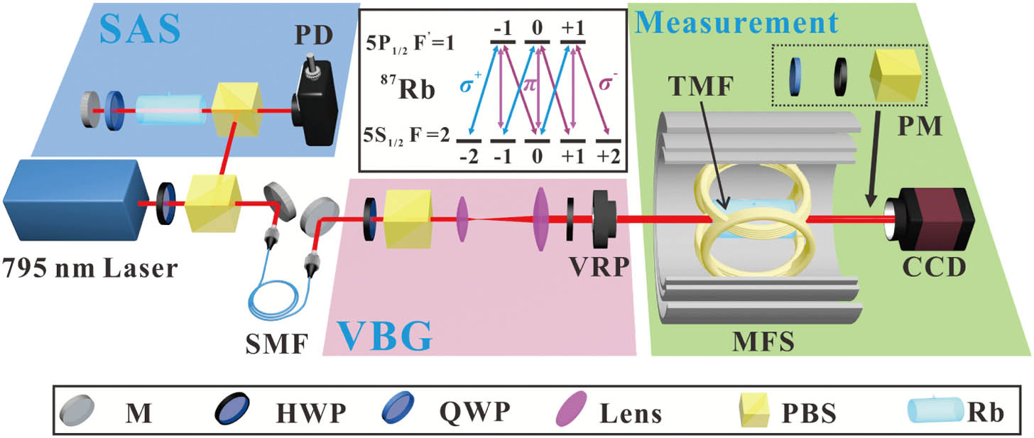
Figure 1.Schematic of the experimental setup and atomic energy levels. M, mirror; HWP, half-wave plate; QWP, quarter-wave plate; L, lens; PBS, polarization beam splitter; PD, photodetector; SMF, single-mode fiber; VRP, vortex retarder plate; CCD, charge-coupled device camera; MFS, magnetic field shielding; PM, projection measurement; SAS, saturated absorption spectroscopy; VBG, vector beam generation.
The polarization distribution of the probe VBs can be reconstructed by measuring the Stokes parameters, which represent the full polarization information of the light [50]. Experimentally, the Stokes parameters can be obtained by using the projection measurement system consisting of a QWP, a polarizer, and a CCD. Figure 2(a) shows the polarization distribution of the generated VB with
![]()
Figure 2.Experimental results of the radially polarized beam in presence of TMF. (a) Intensity and polarization distribution without atoms. (b)–(h) Intensity distributions after passing through atoms under vertical TMF of varying strength:
3. EXPERIMENTAL RESULTS
Now we turn to how the magnetic field influences the interaction between the vector beam and the atoms, the transmission in particular. First, when the magnetic field is not applied, there is very little absorption of the vector beam, as compared with the profile without atoms [Figs. 2(a) and 2(b)]. As a vertical TMF is applied to the atoms, however, a petal-like transmission pattern gradually appears, as shown in Figs. 2(c)–2(h). In general, one predicts
Increasing the magnitude of the TMF, we observe that maximum transmission always occurs in the region where the linear polarization is parallel or antiparallel to the TMF. The strongest absorption occurs in regions where the local linear polarization is perpendicular to the TMF axis, and it increases with increasing magnitude of the TMF. We note that positive and negative TMFs both lead to the same pattern, as atomic transitions respond to the alignment but not orientation of linear polarization. The variation of transparency and absorption is plotted against the TMF strength (from
As expected, the absorption of the optical
![]()
Figure 3.Experimental results of the radially polarized beam in presence of an LMF. (a)–(f) Intensity distributions after passing through the atom vapor under the varied LMF:
The transmitted vector beam, as a whole, is highly sensitive to the TMF however, particularly in regard to the
Figures 4(a) and 4(b) show the relationship between the TMF alignment and the transmitted polarization, as reconstructed from CCD measurements of the Stokes parameters. Figure 4(c) shows the angle of the image axis (green arrow) when rotating the TMF axis from 0 to
![]()
Figure 4.Transmission profiles as functions of TMFs alignment. (a) and (b) Intensity and polarization distributions for vertical and diagonal TMF alignment. (c) Image axis of the transmission profile as a function of TMF alignment. Insets: examples of observed transmission profiles.
To visualize arbitrary magnetic field alignments, we can combine our observations for a TMF and an LMF with further experiments that consider an arbitrary inclination angle,
![]()
Figure 5.Experimental results of the radially polarized beam in presence of the spatial magnetic field with fixed strength (
We then set the strength of the magnetic field to
Thus far, we have considered only radially polarized VBs, but similar observations hold for general VBs. We demonstrate this in Fig. 6 by comparing VBs with differing topological charge:
![]()
Figure 6.Polarization and intensity profiles for VBs with different polarization topological charges
4. THEORETICAL INTERPRETATION AND DISCUSSION
As is now well known, atom–light interaction is strongly polarization-dependent. There are, however, infinitely many ways to decompose a field’s polarization and to choose an atom’s quantization axis. For the former, the spherical basis has many useful properties [26,28,51]. Here, light polarized perpendicularly to the atom’s quantization axis drives a superposition of
Thus, we define the optical field in the spherical basis
A. Interaction under an LMF
As shown in Fig. 7(a), when an LMF is applied, we choose the quantization axis along the LMF, coinciding with the propagation direction of the light. In this case, all the linearly polarized components of the probe VBs are perpendicular to the quantization axis, and the light will connect all Zeeman sublevels of the
![]()
Figure 7.Excitation scheme for (a) the LMF and (d) the TMF. (b) Coherent dark state and (c) decoherent state induced by Zeeman splitting. Bare dark state (e) without and (f) with Zeeman splitting. In presence of the magnetic field, magnetic sublevels are shifted by an amount
When the LMF is zero, the Zeeman sublevels are degenerate, and atoms are pumped into a nonabsorbing state induced by coherent population trapping. This is similar to the case of standard EIT, where the left and right circularly polarized components of an optical field resonate with the atomic levels to form the
B. Interaction under a TMF
When a pure TMF is applied, as shown in Fig. 7(d), the quantization axis is chosen to be aligned with the axis of the TMF. In contrast with the former case, the interaction of the linearly polarized components of the probe VBs is strongly dependent on the azimuthal angle. The components whose linear polarization is parallel to the TMF axis operate on the
C. Interaction with Arbitrarily Oriented B-Fields and Associated Applications
Generally, when
Based on the above analysis, the transmitted pattern of VBs after passing through the atoms is strongly dependent on the
Ultimately, the alignment and strength of a spatial
5. CONCLUSION
In conclusion, we have investigated the transmission properties and pattern formation of vector beams in an atomic vapor, as influenced by a magnetic field. In particular, there are two limiting cases, corresponding to two kinds of dark state. When an LMF is applied, an incoming probe beam undergoes uniform absorption, and the coherence between Zeeman sublevels (coherent dark states) can be destroyed by increasing the strength of the LMF. Applying a TMF, however, will generate bare dark states and produce a petal-like pattern, which is dependent on the azimuthal angle and topological charge of the polarization. The general case, where the magnetic field is applied along an arbitrary axis, is also studied, revealing the general influence of a spatial
Acknowledgment
Acknowledgment. FC and SF-A acknowledge financial support from the European Training Network ColOpt, which is funded by the European Union (EU) Horizon 2020 program under the Marie Sklodowska-Curie Action. TWC acknowledges support by the NKFIH.
References
[1] K.-J. Boller, A. Imamoğlu, S. E. Harris. Observation of electromagnetically induced transparency. Phys. Rev. Lett., 66, 2593-2596(1991).
[2] D. J. Fulton, R. R. Moseley, S. Shepherd, B. D. Sinclair, M. H. Dunn. Effects of Zeeman splitting on electromagnetically-induced transparency. Opt. Commun., 116, 231-239(1995).
[3] S. A. Lezama, A. M. Akulshin. Electromagnetically induced absorption. Phys. Rev. A, 59, 4732-4735(1999).
[4] F. Renzoni, W. Maichen, L. Windholz, E. Arimondo. Coherent population trapping with losses observed on the Hanle effect of the d1 sodium line. Phys. Rev. A, 55, 3710-3718(1997).
[5] J. Kitching, S. Knappe, E. A. Donley. Atomic sensors–a review. IEEE Sens. J., 11, 1749-1758(2011).
[6] R. Wiesendanger. Single-atom magnetometry. Curr. Opin. Solid State Mater. Sci., 15, 1-7(2011).
[7] D. Drung, R. Cantor, M. Peters, H. Scheer, H. Koch. Low-noise high-speed dc superconducting quantum interference device magnetometer with simplified feedback electronics. Appl. Phys. Lett., 57, 406-408(1990).
[8] M. Pannetier, C. Fermon, G. Le Goff, J. Simola, E. Kerr. Femtotesla magnetic field measurement with magnetoresistive sensors. Science, 304, 1648-1650(2004).
[9] I. Kominis, T. Kornack, J. Allred, M. V. Romalis. A subfemtotesla multichannel atomic magnetometer. Nature, 422, 596-599(2003).
[10] M. Fleischhauer, M. O. Scully. Quantum sensitivity limits of an optical magnetometer based on atomic phase coherence. Phys. Rev. A, 49, 1973-1986(1994).
[11] E. Alipieva, S. Gateva, E. Taskova, S. Cartaleva. Narrow structure in the coherent population trapping resonance in rubidium. Opt. Lett., 28, 1817-1819(2003).
[12] S. Gateva, L. Petrov, E. Alipieva, G. Todorov, V. Domelunksen, V. Polischuk. Shape of the coherent-population-trapping resonances and high-rank polarization moments. Phys. Rev. A, 76, 025401(2007).
[13] V. Acosta, M. Ledbetter, S. Rochester, D. Budker, D. J. Kimball, D. Hovde, W. Gawlik, S. Pustelny, J. Zachorowski, V. Yashchuk. Nonlinear magneto-optical rotation with frequency-modulated light in the geophysical field range. Phys. Rev. A, 73, 053404(2006).
[14] S. Afach, G. Ban, G. Bison, K. Bodek, Z. Chowdhuri, Z. D. Grujić, L. Hayen, V. Hélaine, M. Kasprzak, K. Kirch, P. Knowles, H.-C. Koch, S. Komposch, A. Kozela, J. Krempel, B. Lauss, T. Lefort, Y. Lemière, A. Mtchedlishvili, O. Naviliat-Cuncic, F. M. Piegsa, P. N. Prashanth, G. Quéméner, M. Rawlik, D. Ries, S. Roccia, D. Rozpedzik, P. Schmidt-Wellenburg, N. Severjins, A. Weis, E. Wursten, G. Wyszynski, J. Zejma, G. Zsigmond. Highly stable atomic vector magnetometer based on free spin precession. Opt. Express, 23, 22108-22115(2015).
[15] G. Bison, V. Bondar, P. Schmidt-Wellenburg, A. Schnabel, J. Voigt. Sensitive and stable vector magnetometer for operation in zero and finite fields. Opt. Express, 26, 17350-17359(2018).
[16] G. Zhang, S. Huang, F. Xu, Z. Hu, Q. Lin. Multi-channel spin exchange relaxation free magnetometer towards two-dimensional vector magnetoencephalography. Opt. Express, 27, 597-607(2019).
[17] I. Novikova, A. Matsko, V. Velichansky, M. O. Scully, G. R. Welch. Compensation of ac stark shifts in optical magnetometry. Phys. Rev. A, 63, 063802(2001).
[18] S. Pustelny, D. J. Kimball, S. Rochester, V. Yashchuk, W. Gawlik, D. Budker. Pump-probe nonlinear magneto-optical rotation with frequency-modulated light. Phys. Rev. A, 73, 023817(2006).
[19] D. Budker, V. Yashchuk, M. Zolotorev. Nonlinear magneto-optic effects with ultranarrow widths. Phys. Rev. Lett., 81, 5788-5791(1998).
[20] D. Budker, D. Kimball, S. Rochester, V. Yashchuk, M. Zolotorev. Sensitive magnetometry based on nonlinear magneto-optical rotation. Phys. Rev. A, 62, 043403(2000).
[21] I. Novikova, A. Matsko, V. Sautenkov, V. Velichansky, G. Welch, M. Scully. Ac-Stark shifts in the nonlinear Faraday effect. Opt. Lett., 25, 1651-1653(2000).
[22] S. Pustelny, A. Wojciechowski, M. Gring, M. Kotyrba, J. Zachorowski, W. Gawlik. Magnetometry based on nonlinear magneto-optical rotation with amplitude-modulated light. J. Appl. Phys., 103, 063108(2008).
[23] V. Shah, S. Knappe, P. D. Schwindt, J. Kitching. Subpicotesla atomic magnetometry with a microfabricated vapour cell. Nat. Photonics, 1, 649-652(2007).
[24] D. Budker, M. Romalis. Optical magnetometry. Nat. Phys., 3, 227-234(2007).
[25] D. Le Sage, K. Arai, D. R. Glenn, S. J. DeVience, L. M. Pham, L. Rahn-Lee, M. D. Lukin, A. Yacoby, A. Komeili, R. L. Walsworth. Optical magnetic imaging of living cells. Nature, 496, 486-489(2013).
[26] H. Lee, M. Fleischhauer, M. O. Scully. Sensitive detection of magnetic fields including their orientation with a magnetometer based on atomic phase coherence. Phys. Rev. A, 58, 2587-2595(1998).
[27] J. Dimitrijević, A. Krmpot, M. Mijailović, D. Arsenović, B. Panić, Z. Grujić, B. Jelenković. Role of transverse magnetic fields in electromagnetically induced absorption for elliptically polarized light. Phys. Rev. A, 77, 013814(2008).
[28] V. Yudin, A. Taichenachev, Y. Dudin, V. Velichansky, A. Zibrov, S. Zibrov. Vector magnetometry based on electromagnetically induced transparency in linearly polarized light. Phys. Rev. A, 82, 033807(2010).
[29] K. Cox, V. I. Yudin, A. V. Taichenachev, I. Novikova, E. E. Mikhailov. Measurements of the magnetic field vector using multiple electromagnetically induced transparency resonances in Rb vapor. Phys. Rev. A, 83, 015801(2011).
[30] L. Margalit, M. Rosenbluh, A. Wilson-Gordon. Degenerate two-level system in the presence of a transverse magnetic field. Phys. Rev. A, 87, 033808(2013).
[31] Q. Zhan. Cylindrical vector beams: from mathematical concepts to applications. Adv. Opt. Photon., 1, 1-57(2009).
[32] J. Wang, F. Castellucci, S. Franke-Arnold. Vectorial light–matter interaction: exploring spatially structured complex light fields. AVS Quantum Sci., 2, 031702(2020).
[33] F. K. Fatemi. Cylindrical vector beams for rapid polarization-dependent measurements in atomic systems. Opt. Express, 19, 25143-25150(2011).
[34] J. Wang, X. Yang, Y. Li, Y. Chen, M. Cao, D. Wei, H. Gao, F. Li. Optically spatial information selection with hybridly polarized beam in atomic vapor. Photon. Res., 6, 451-456(2018).
[35] X. Yang, A. Fang, J. Wang, Y. Li, X. Chen, X. Zhang, M. Cao, D. Wei, K. Müller-Dethlefs, H. Gao, F. Li. Manipulating the transmission of vector beam with spatially polarized atomic ensemble. Opt. Express, 27, 3900-3908(2019).
[36] J. Wang, X. Yang, Z. Dou, S. Qiu, J. Liu, Y. Chen, M. Cao, H. Chen, D. Wei, K. Müller-Dethlefs, H. Gao, F. Li. Directly extracting the authentic basis of cylindrical vector beams by a pump-probe technique in an atomic vapor. Appl. Phys. Lett., 115, 221101(2019).
[37] J. Wang, Y. Chen, X. Yang, J. Liu, S. Qiu, M. Cao, H. Chen, D. Wei, K. Müller-Dethlefs, H. Gao, F. Li. Optically polarized selection in atomic vapor and its application in mapping the polarization distribution. J. Phys. Commun., 4, 015019(2020).
[38] S. Shi, D.-S. Ding, Z.-Y. Zhou, Y. Li, W. Zhang, B.-S. Shi. Magnetic-field-induced rotation of light with orbital angular momentum. Appl. Phys. Lett., 106, 261110(2015).
[39] L. Stern, A. Szapiro, E. Talker, U. Levy. Controlling the interactions of space-variant polarization beams with rubidium vapor using external magnetic fields. Opt. Express, 24, 4834-4841(2016).
[40] F. Bouchard, H. Larocque, A. M. Yao, C. Travis, I. De Leon, A. Rubano, E. Karimi, G.-L. Oppo, R. W. Boyd. Polarization shaping for control of nonlinear propagation. Phys. Rev. Lett., 117, 233903(2016).
[41] H. Hu, D. Luo, H. Chen. Nonlinear frequency conversion of vector beams with four wave mixing in atomic vapor. Appl. Phys. Lett., 115, 211101(2019).
[42] V. Parigi, V. D’Ambrosio, C. Arnold, L. Marrucci, F. Sciarrino, J. Laurat. Storage and retrieval of vector beams of light in a multiple-degree-of-freedom quantum memory. Nat. Commun., 6, 7706(2015).
[43] Y.-H. Ye, M.-X. Dong, Y.-C. Yu, D.-S. Ding, B.-S. Shi. Experimental realization of optical storage of vector beams of light in warm atomic vapor. Opt. Lett., 44, 1528-1531(2019).
[44] N. Radwell, T. W. Clark, B. Piccirillo, S. M. Barnett, S. Franke-Arnold. Spatially dependent electromagnetically induced transparency. Phys. Rev. Lett., 114, 123603(2015).
[45] X. Yang, Y. Chen, J. Wang, Z. Dou, M. Cao, D. Wei, H. Batelaan, H. Gao, F. Li. Observing quantum coherence induced transparency of hybrid vector beams in atomic vapor. Opt. Lett., 44, 2911-2914(2019).
[46] T. W. Clark. Sculpting shadows on the spatial structuring of fields & atoms: a tale of light and darkness(2016).
[47] F. Castellucci, T. W. Clark, A. Selyem, J. Wang, S. Franke-Arnold. An atomic compass–detecting 3D magnetic field alignment with vector vortex light(2021).
[48] L. Marrucci, C. Manzo, D. Paparo. Optical spin-to-orbital angular momentum conversion in inhomogeneous anisotropic media. Phys. Rev. Lett., 96, 163905(2006).
[49] L. Marrucci, C. Manzo, D. Paparo. Pancharatnam-Berry phase optical elements for wave front shaping in the visible domain: switchable helical mode generation. Appl. Phys. Lett., 88, 221102(2006).
[50] G. Milione, H. Sztul, D. Nolan, R. Alfano. Higher-order Poincaré sphere, Stokes parameters, and the angular momentum of light. Phys. Rev. Lett., 107, 053601(2011).
[51] M. Auzinsh, D. Budker, S. Rochester. Optically Polarized Atoms: Understanding Light-Atom Interactions(2010).
[52] Y. Dancheva, G. Alzetta, S. Cartaleva, M. Taslakov, C. Andreeva. Coherent effects on the Zeeman sublevels of hyperfine states in optical pumping of Rb by monomode diode laser. Opt. Commun., 178, 103-110(2000).
[53] R. Meshulam, T. Zigdon, A. Wilson-Gordon, H. Friedmann. Transfer-of-coherence-enhanced stimulated emission and electromagnetically induced absorption in Zeeman split
[54] J. Anupriya, N. Ram, M. Pattabiraman. Hanle electromagnetically induced transparency and absorption resonances with a Laguerre Gaussian beam. Phys. Rev. A, 81, 043804(2010).
[55] W. Happer. Optical pumping. Rev. Mod. Phys., 44, 169-249(1972).
[56] A. Huss, R. Lammegger, L. Windholz, E. Alipieva, S. Gateva, L. Petrov, E. Taskova, G. Todorov. Polarization-dependent sensitivity of level-crossing, coherent-population-trapping resonances to stray magnetic fields. J. Opt. Soc. Am. B, 23, 1729-1736(2006).
[57] L. Yin, B. Luo, J. Xiong, H. Guo. Tunable rubidium excited state Voigt atomic optical filter. Opt. Express, 24, 6088-6093(2016).
[58] A. Selyem. Three-dimensional light sculptures and their interaction with atomic media: an experimentalist’s guide(2019).
[59] Y. Chen, K.-Y. Xia, W.-G. Shen, J. Gao, Z.-Q. Yan, Z.-Q. Jiao, J.-P. Dou, H. Tang, Y.-Q. Lu, X.-M. Jin. Vector vortex beam emitter embedded in a photonic chip. Phys. Rev. Lett., 124, 153601(2020).
[60] C. L. Garrido Alzar. Compact chip-scale guided cold atom gyrometers for inertial navigation: enabling technologies and design study. AVS Quantum Sci., 1, 014702(2019).
[61] L. Stern, D. G. Bopp, S. A. Schima, V. N. Maurice, J. E. Kitching. Chip-scale atomic diffractive optical elements. Nat. Commun., 10, 1(2019).
[62] J. P. Mcgilligan, K. Moore, A. Dellis, G. Martinez, E. de Clercq, P. Griffin, A. Arnold, E. Riis, R. Boudot, J. Kitching. Laser cooling in a chip-scale platform. Appl. Phys. Lett., 117, 054001(2020).
[63] B. Chen, X. Hou, F. Ge, X. Zhang, Y. Ji, H. Li, P. Qian, Y. Wang, N. Xu, J. Du. Calibration-free vector magnetometry using nitrogen-vacancy center in diamond integrated with optical vortex beam. Nano Lett., 20, 8267-8272(2020).


Set citation alerts for the article
Please enter your email address

© Copyright 2018-2021 | Chinese Laser Press. All Rights Reserved 沪ICP备15018463号-20