
Pengfei Liu, Linhao Ren, Hao Wen, Lei Shi, Xinliang Zhang. Progress in integrated electro-optic frequency combs (Invited)[J]. Infrared and Laser Engineering, 2022, 51(5): 20220381
- Infrared and Laser Engineering
- Vol. 51, Issue 5, 20220381 (2022)
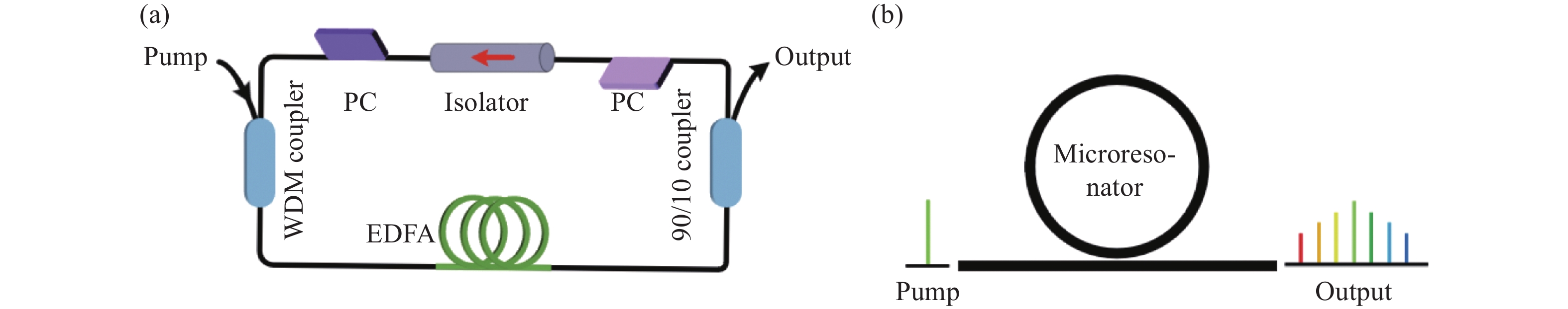
Fig. 1. Schematic of optical frequency comb generators. (a) Typical self-starting mode-locked fiber laser; (b) On-chip optical frequency comb generation based on Kerr microresonators
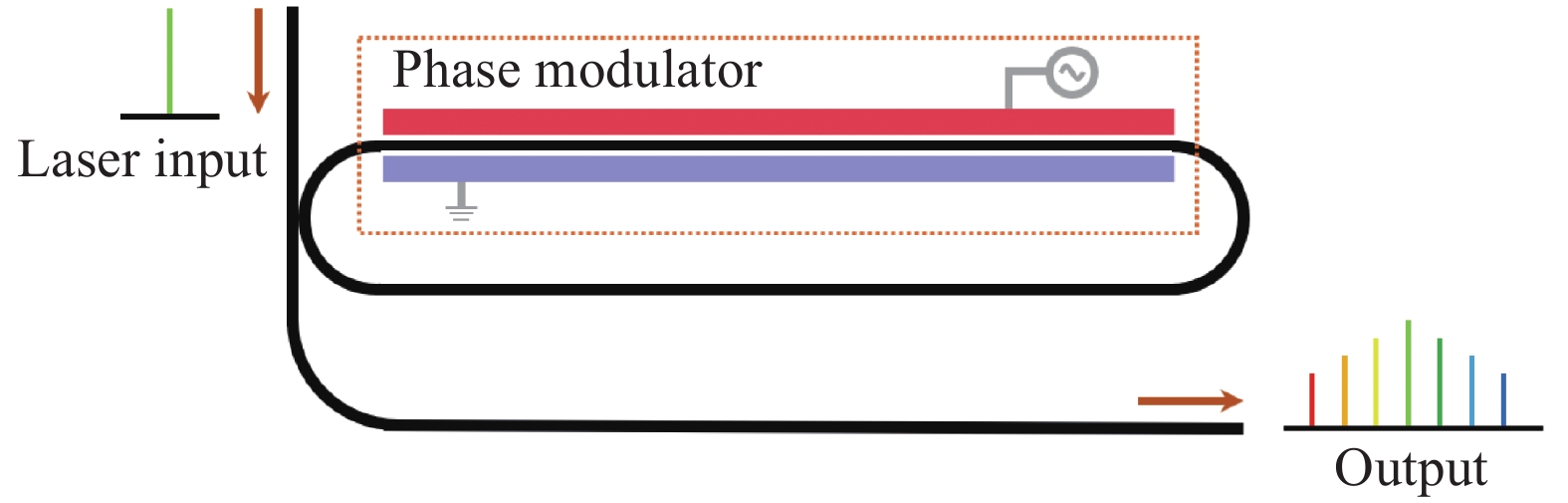
Fig. 2. Schematic of an integrated electro-optic frequency comb generator
Fig. 3. Schematic of electro-optic modulators.(a) Single-phase modulator;(b) Dual-drive Mach-Zehnder modulator
Fig. 4. (a) Frequency spectrum of a single-phase modulator;(b) Frequency spectrum of a DD-MZM
Fig. 5. (a) Schematic of an microring intracavity modulator; (b) Schematic of a coupling-modulated modulator
Fig. 6. Flow chart of the smart-cut process for a LNOI wafer[66]
Fig. 7. Integrated EO comb generator and its output spectrum based on LNOI[67]. (a) Optical micrograph of a fabricated lithium niobate microring resonator; (b) Measured output spectrum of the EO comb generated from the microring resonator, demonstrating a bandwidth exceeding 80 nm and more than 900 comb lines with a slope of 1 dB·nm−1
Fig. 8. Schematic of mid-infrared frequency combs generator based on LNOI and their corresponding spectrums[69]. (a) Design 1, the DFG process occurs outside the microring resonator; (b) Power spectrum of the output mid-infrared frequency comb for modulation coefficient β =1.2π in design 1; (c) Design 2, the DFG process occurs in the microring resonator; (d) Power spectrum of the output mid-infrared frequency comb for modulation coefficient β =0.4π in design 2
Fig. 9. Schematic of an InP integrated EO comb generator[48]. (a) Integrated comb generator PIC schematic; (b) Optical micrograph of the fabricated PIC (Photonic integrated chip, PIC) (Footprint: 4.5 mm× 2.5 mm); (c) PIC-PCB assembly
Fig. 10. Schematic of MRM integrated EO comb[99]. (a) Optical micrograph of a microring resonator modulator (Footprint of the MRM and electrical pads: 0.062 mm2); (b) Schematic of waveguide cross section; (c) Generated EO frequency comb at 10 GHz line spacing for a 0.22 V forward bias voltage applied
Fig. 11. Schematic of cascaded MRM integrated EO comb[100]. (a) Schematic of the proposed MRM; (b) Cross-section schematic of the PN junction of the microring; (c) Experimental setup; (d) Comb spectrum demonstrating 5 lines when driving MRM 1 at 20 GHz and MRM 2 at 10 GHz
Fig. 12. Schematic of cascaded MZM integrated EO comb generator[53]. (a) Schematic of the cascaded MZMs optical frequency comb generation, the inset shows the cross-sectional view of active arms in the MZM; (b) Measured optical spectrum of the 9-line OFC; (c) Measured Nyquist pulses in the time domain; (d) Comparison of the measured single Nyquist pulse (red solid line) with the calculated theoretical pulse (black dashed line)
Fig. 13. Schematic of EOFC for WDM[111]. (a) Illustration of the dual-drive MZM design; (b) Cross section schematic of MZM phase shifter; (c) Output spectrum of generated 5-line comb with 20 GHz spacing; (d) BER of Nyquist-WDM signals of 5×16 Gbaud 16/32 QAM and 5 × 20 Gbaud 16 QAM
Fig. 14. Schematic of MRM for WDM[96]. (a) Schematic of a flexible-grid WDM silicon photonic transmitter based on cascaded MRMs; (b) Experimental setup for optical comb generation, data transmission, and characterization; (c) Spectrum after data transmission when MRM1 is aligned at 20 GHz comb line with channel 1 (1554 nm), channel 2 (1554.16 nm), and channel 3 (1553.84 nm)
Fig. 15. Schematic of EOFC based on LNOI for DCS[116]. (a) Scheme of DCS with integrated EO microrings (AOFS: acousto-optic frequency shifter, BS: beam splitter, BD: balanced detector, DAU: data acquisition Unit); (b) Measured dual comb spectrum with a measurement time of 195 s; (c) Measured absorption spectra of the acetylene
Fig. 16. Schematic of EOFC based on MZM for DCS[98]. (a) Top-view schematic of the 4-mm long Si single-drive push-pull MZM; (b) Beat notes for f RF= 1 GHz and Δf RF = 4 MHz; (c) Experimentally measured transfer function of optical bandpass filter

Set citation alerts for the article
Please enter your email address
© Copyright 2018-2021 | Chinese Laser Press. All Rights Reserved 沪ICP备15018463号-20