• Photonics Research
  • Vol. 10, Issue 9, 2066 (2022)
Xingyu Chen, Rongbin Su*, Jin Liu, Juntao Li, and Xue-Hua Wang
Author Affiliations
  • State Key Laboratory of Optoelectronic Materials and Technologies, School of Physics, Sun Yat-sen University, Guangzhou 510000, China
  • show less
    DOI: 10.1364/PRJ.462318 Cite this Article Set citation alerts
    Xingyu Chen, Rongbin Su, Jin Liu, Juntao Li, Xue-Hua Wang. Scalable and highly efficient approach for an on-chip single-photon source[J]. Photonics Research, 2022, 10(9): 2066 Copy Citation Text show less
    Schematic diagram of elliptical Bragg resonator with coupling waveguides for generation of on-chip single photons. (a) The elliptical Bragg resonator with coupling waveguides consists of an elliptical disk with quantum emitter in the center, fully etched elliptical Bragg gratings, and coupling waveguides on the long axis of the elliptical disk. The substrate of the structure is a thick low-refractive-index layer (e.g., silica). (b) Cross section with superimposed cavity mode electric field of the elliptical Bragg resonator with coupling waveguides in x direction. Rx is the radius of the central disk on x axis (long axis). P, W, period and grating spacing of the Bragg grating, respectively; T, thickness of the structure. (c) Cross section with superimposed cavity mode electric field of the elliptical Bragg resonator with coupling waveguide in y direction. Ry is the radius of the central disk on the y axis (short axis).
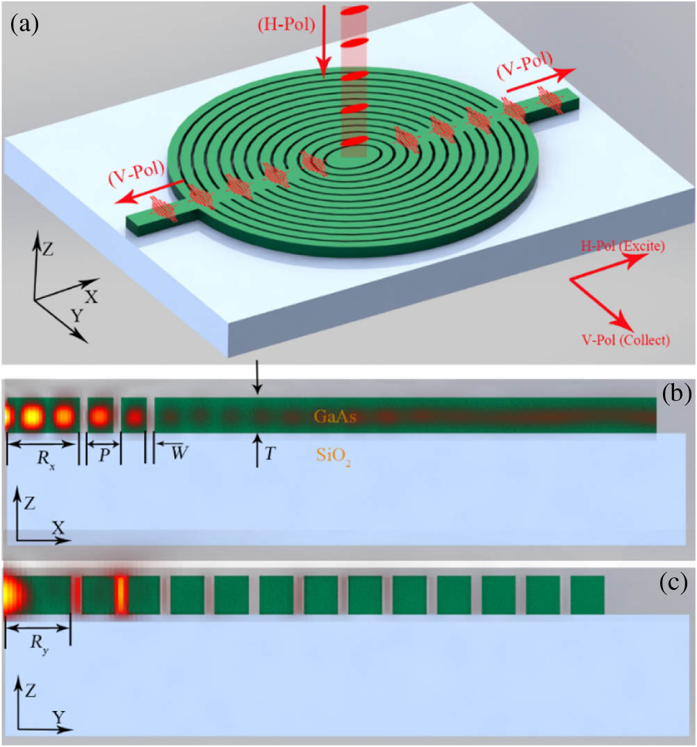
    Fig. 1. Schematic diagram of elliptical Bragg resonator with coupling waveguides for generation of on-chip single photons. (a) The elliptical Bragg resonator with coupling waveguides consists of an elliptical disk with quantum emitter in the center, fully etched elliptical Bragg gratings, and coupling waveguides on the long axis of the elliptical disk. The substrate of the structure is a thick low-refractive-index layer (e.g., silica). (b) Cross section with superimposed cavity mode electric field of the elliptical Bragg resonator with coupling waveguides in x direction. Rx is the radius of the central disk on x axis (long axis). P, W, period and grating spacing of the Bragg grating, respectively; T, thickness of the structure. (c) Cross section with superimposed cavity mode electric field of the elliptical Bragg resonator with coupling waveguide in y direction. Ry is the radius of the central disk on the y axis (short axis).
    Purcell factor distribution and polarization efficiency of the resonator with different ellipticities. Purcell factor as a function of wavelength with different ellipticities of (a) ρ=0, (b) ρ=1%, (c) ρ=5%, and (d) ρ=20%. Points A, B1, B2, C1, C2, and D are the Purcell factor peaks of the resonators with different ellipticities, also shown in (e). (e) Polarization efficiency of preparing V-Pol single photons for a QD coupling to the resonator with different ellipticities. Yellow and red lines correspond to cavity peaks, i.e., Purcell factor peaks of V and H modes, respectively. The blue curve represents 95% polarization efficiency contour line. In simulations, the radius of the central disk on x axis (long axis) is selected as Rx=398 nm.
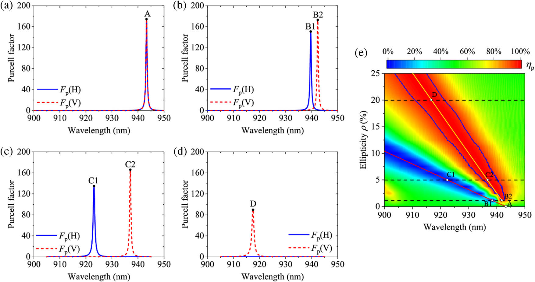
    Fig. 2. Purcell factor distribution and polarization efficiency of the resonator with different ellipticities. Purcell factor as a function of wavelength with different ellipticities of (a) ρ=0, (b) ρ=1%, (c) ρ=5%, and (d) ρ=20%. Points A, B1, B2, C1, C2, and D are the Purcell factor peaks of the resonators with different ellipticities, also shown in (e). (e) Polarization efficiency of preparing V-Pol single photons for a QD coupling to the resonator with different ellipticities. Yellow and red lines correspond to cavity peaks, i.e., Purcell factor peaks of V and H modes, respectively. The blue curve represents 95% polarization efficiency contour line. In simulations, the radius of the central disk on x axis (long axis) is selected as Rx=398  nm.
    Elliptical Bragg resonator with coupling waveguide for coupling polarized single photons. The β-factor as a function of wavelength for different (a) widths of the waveguide Wd and (b) values of ellipticity ρ. The area between the black solid lines corresponds to the V mode with Purcell factor >5. Blue and green dashed curves represent the 0.7 and 0.8 β-factor contour line, respectively. The ellipticity ρ and waveguide width Wd in (a) and (b) are set to 20% and 485 nm, respectively. The red lines in (a) and (b) correspond to Wd=485 nm and ρ=20%, respectively. (c) On-chip coupling efficiency η (blue line) and Purcell factor of cavity V mode (red line) as a function of wavelength with the parameters of Wd=485 nm and ρ=20%. (d) Polarization efficiency ηp (blue solid line), β-factor (blue dashed dotted line), and extinction ratio Tp (red line) as a function of wavelength with parameters of Wd=485 nm and ρ=20%. The green shaded spectral region indicates spectral random distribution of QD emission from 914 nm to 923 nm.
    Fig. 3. Elliptical Bragg resonator with coupling waveguide for coupling polarized single photons. The β-factor as a function of wavelength for different (a) widths of the waveguide Wd and (b) values of ellipticity ρ. The area between the black solid lines corresponds to the V mode with Purcell factor >5. Blue and green dashed curves represent the 0.7 and 0.8 β-factor contour line, respectively. The ellipticity ρ and waveguide width Wd in (a) and (b) are set to 20% and 485 nm, respectively. The red lines in (a) and (b) correspond to Wd=485  nm and ρ=20%, respectively. (c) On-chip coupling efficiency η (blue line) and Purcell factor of cavity V mode (red line) as a function of wavelength with the parameters of Wd=485  nm and ρ=20%. (d) Polarization efficiency ηp (blue solid line), β-factor (blue dashed dotted line), and extinction ratio Tp (red line) as a function of wavelength with parameters of Wd=485  nm and ρ=20%. The green shaded spectral region indicates spectral random distribution of QD emission from 914 nm to 923 nm.
    Robustness of the elliptical Bragg resonator with coupling waveguide on SiO2 substrate for on-chip single-photon source. On-chip coupling efficiency as a function of wavelength with QD position deviation in (a) x direction and (b) y direction from the resonator center. (c)–(e) Electric field distribution at a wavelength of 921 nm with different QD deviations. Insets show the position of QDs (green dots) and the electric field distribution of the center disk.
    Fig. 4. Robustness of the elliptical Bragg resonator with coupling waveguide on SiO2 substrate for on-chip single-photon source. On-chip coupling efficiency as a function of wavelength with QD position deviation in (a) x direction and (b) y direction from the resonator center. (c)–(e) Electric field distribution at a wavelength of 921 nm with different QD deviations. Insets show the position of QDs (green dots) and the electric field distribution of the center disk.
    Diffraction of (a) first-order and (b) second-order Bragg gratings. The yellow bold arrow indicates the initial light propagating wave vector. Black arrows superimposed on grating are the corresponding reciprocal lattice vector G.
    Fig. 5. Diffraction of (a) first-order and (b) second-order Bragg gratings. The yellow bold arrow indicates the initial light propagating wave vector. Black arrows superimposed on grating are the corresponding reciprocal lattice vector G.
    Xingyu Chen, Rongbin Su, Jin Liu, Juntao Li, Xue-Hua Wang. Scalable and highly efficient approach for an on-chip single-photon source[J]. Photonics Research, 2022, 10(9): 2066
    Download Citation