
Yujia Li, Jianshi Tang, Bin Gao, Xinyi Li, Yue Xi, Wanrong Zhang, He Qian, Huaqiang Wu. Oscillation neuron based on a low-variability threshold switching device for high-performance neuromorphic computing[J]. Journal of Semiconductors, 2021, 42(6): 064101
- Journal of Semiconductors
- Vol. 42, Issue 6, 064101 (2021)
Abstract
1. Introduction
A resistive random-access memory (RRAM)-based neural network has been extensively studied as a promising solution to overcome the von Neumann bottleneck faced in conventional artificial intelligence (AI) hardware[
Recently, a compact oscillation neuron based on a metal–insulator transition (MIT) threshold switching (TS) device was proposed as a more scalable artificial neuron[
In this work, we further implement an oscillation neuron using the HfO2/Ag NDs TS device. This neuron exhibits self-oscillation behavior at low applied voltage (1 V), where the oscillation frequency increases with the applied voltage and decreases with the load resistance. In addition, it can work with a large RRAM crossbar array (> 128 × 128) owing to the high on/off ratio (> 108) of Ag NDs TS device. Moreover, in the neural network simulation, a high recognition accuracy (loss < 1%) can be achieved by using this oscillation neuron because of its high uniformity.
2. Results and discussion
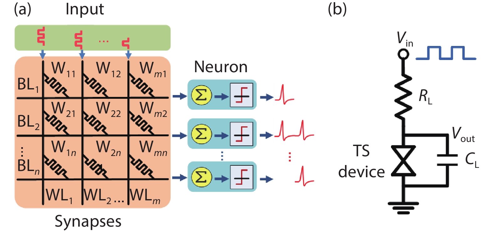
Fig. 1(a) illustrates the schematic diagram of a simple artificial neural network. When the input voltages are applied to the crossbar synaptic array, the weighted sum currents are integrated by the neurons at the end of each column (BL) and trigger output spike firing when they reach the neuron thresholds. The circuit implementation of the oscillation neuron based on the TS device is shown in Fig. 1(b). The load resistance (RL) represents the RRAM synaptic weight connected in series with the TS device. Also, CL is the load capacitance including parallel capacitance and parasitic capacitance at the neuron node. Initially, the TS device is in the off state (Roff). When applying an input voltage pulse (Vin), the voltage mainly drops on the TS device since Roff > RL, and CL starts to charge. When Vin is larger than the threshold voltage of the TS device Vth, it turns to the on state (Ron), and then CL starts to discharge since the voltage drop on the TS device is reduced (Ron < RL). Once the voltage drop on the TS device is below the hold voltage of TS device Vhold, it switches back to Roff, ready for the next firing event. In this way, the TS device switches on and off between Ron and Roff, and the neuron outputs oscillation signal. If RL is chosen to satisfy Roff > > RL > > Ron, the ideal oscillation frequency f can be described as[
![]()
Figure 1.(Color online) (a) Schematic diagram of a typical artificial neural network. (b) Circuit implementation of the oscillation neuron with a TS device.
Eq. (1) shows a one-to-one correspondence between f and RL at a certain CL and Vin. Therefore, the oscillation frequency can be used to represent the weight of the RRAM synapse accurately.
In this study, we demonstrate the oscillation neuron using the Ag NDs TS device based on ECM filaments. The devices were fabricated with a cell size of 10 × 10 μm2. The bottom electrode was patterned by photolithography and deposited by sputtering of 5 nm Ti and 50 nm Pt. An 8 nm thick HfO2 dielectric was deposited by atomic layer deposition (ALD) at 250 °C. The Ag NDs with diameters of 50 nm were patterned by e-beam lithography (EBL) and deposited by sputtering. A 40 nm-thick Pt was deposited as the top electrode. The transmission electron microscope (TEM) image of the Ag NDs TS device is shown in Fig. 2(a). Fig. 2(b) exhibits the schematic illustration of the threshold switching process in the device. In the initial state, there is no conductive filament in the dielectric layer, and the device is in the high-resistance state (HRS). When applying a voltage (Vappl) larger than Vth, the electric field is locally enhanced in the areas with Ag NDs, so the Ag atoms are easier to be ionized as the ion source (Ag → Ag+ + e−) for diffusing toward the bottom electrode, which leads to the formation of metallic filaments and turns the device to a low-resistance state (LRS). In this device, the Ag filaments are thin and unstable due to the small amount of Ag ions. Spontaneous rupture of the filaments occurs immediately when Vappl goes below Vhold, which turns the device back to HRS. In this process, the Ag atoms form clusters on the trace of filaments. Owing to the highly ordered Ag NDs, Ag filaments tend to form at the same positions and the formed filaments would have similar morphology, in different operation cycles or different devices. Fig. 2(c) shows the typical current–voltage (I–V) curve of the Ag NDs TS device under voltage sweeps between 0 and 1 V. This device exhibits a low leakage current less than 1 pA and large selectivity over 108. The Vth and Vhold of Ag NDs TS device are 0.6 and 0.2 V, respectively, which are carefully tuned to work with the RRAM synapse. In order to evaluate the uniformity of the Ag NDs TS device, the distributions of Vth and Vhold are analyzed, and the cumulative probability of Vth and Vhold is shown in Fig. 2(d). The coefficient of variation is defined as CV = σ/μ to evaluate the variation, where μ and σ are the mean and standard deviation, respectively. This Ag NDs TS device exhibits excellent uniformity (CV < 10%) compared to other TS devices based on ECM filaments [
![]()
Figure 2.(Color online) (a) TEM image of the Ag NDs TS device. (b) Schematic illustration of the threshold switching process in the device. (c) Typical current–voltage (
More systematic studies on the oscillation neuron characteristics are performed as shown in Fig. 3. Fig. 3(a) shows the oscillation waveforms at different input pulse voltages when RL = 50 kΩ and CL = 750 pF. The oscillation frequencies are 31.6, 40.2, 46.9 and 51.4 kHz for Vin = 1, 1.2, 1.4, and 1.6 V, respectively. It is found that the oscillation frequency increases as a function of the pulse amplitude of Vin as described in Eq. (1), and shows good consistency with the simulation results, as shown in Fig. 3(b). Similarly, Fig. 3(c) shows the oscillation waveforms of the Ag NDs TS devices with different RL values (i.e., different synaptic weights) when Vin = 1.2 V and CL = 750 pF. The oscillation frequencies are 40.2, 30.5, 26.1 and 16.8 kHz for RL = 50, 80, 100 and 150 kΩ, respectively. The oscillation frequency decreases as RL increases, as shown in Fig. 3(d). The test results indicate that this Ag NDs TS oscillation neuron exhibits self-oscillation behavior, and the output oscillation frequency can be used to sense the weight of the RRAM synapse accurately when the neuron is connected to the crossbar array.
![]()
Figure 3.(Color online) (a) Oscillation waveforms of the oscillation neuron with different
Based on experimentally derived device data, a model of the RRAM crossbar array is developed to evaluate synaptic weights of different array sizes. Then SIPCE simulation is used to investigate the relationship between the oscillation frequency and the RRAM crossbar array size. In order to simplify the simulation process, the resistance RRAM device is fixed at an intermediate resistance state (RL = 500 kΩ), and Vin is applied to all the word lines (WLs) in parallel. The results are shown in Fig. 4. If the on/off ratio of the TS device is less than 100, only a limited range of the weighted sum could meet the criterion for oscillation (Roff > RL > Ron). It means that the oscillation neuron can only be used for small crossbar arrays (< 16 × 16). With the increase of on/off ratio, the oscillation neuron can work with a wider range of load resistance. Therefore, the weighted sum in a larger RRAM crossbar array can be successfully identified by distinguishable oscillation frequency. As in the case of our present Ag NDs TS device with on/off ratio > 108, it can work with a large RRAM crossbar array of size > 128 × 128.
![]()
Figure 4.(Color online) The oscillation frequency as a function of the RRAM crossbar array size under different on/off ratios of the TS device.
In order to investigate the impact of TS device variation on the oscillation neuron, the oscillation frequency distribution with different CV under the same experimental conditions is shown in Fig. 5(a). The uniformity of the TS device deteriorates with the increase of CV, which leads to a large variation of the oscillation frequency under the same load condition. Fig. 5(b) shows the oscillation frequency distribution of different RL with different TS devices. Compared with the Ag thin film device (CV ~ 30%)[
![]()
Figure 5.(Color online) (a) The oscillation frequency distribution under different
In order to further analyze the impact of the TS device’s uniformity on the artificial neural network, a multi-layer perceptron (MLP) of 784 × 200 × 10 is simulated to classify the handwritten digits in the Modified National Institute of Standards and Technology (MNIST) dataset, as shown in Fig. 6(a)[
![]()
Figure 6.(Color online) (a) The structure of MLP neural network. (b) Simulation results of the MNIST recognition accuracy loss as a function of the variability of the TS device.
3. Conclusion
In conclusion, we have demonstrated a reliable oscillation neuron using the low-variability Ag NDs TS device for high-performance neuromorphic computing. This neuron exhibits self-oscillation behavior at low applied voltages down to 1 V. A systematic study on the oscillation characteristics reveals that the oscillation frequency increases with the applied voltage and also the synaptic conductance connected as the load resistor. The high uniformity and large on/off ratio of the Ag NDs TS device enable the oscillation neuron to reduce the neural network accuracy loss (< 1%) and make it applicable to a large-scale RRAM crossbar array (> 128 × 128). The developed oscillation neuron hence has great potential for future neuromorphic system applications.
Acknowledgements
This work was supported in part by China Key Research and Development Program (2016YFA0201800), and the National Natural Science Foundation of China (91964104, 61974081).
References
[1] G Indiveri, B Linares-Barranco, R Legenstein et al. Integration of nanoscale memristor synapses in neuromorphic computing architectures. Nanotechnology, 24, 384010(2013).
[2] S Ambrogio, S Balatti, V Milo et al. Neuromorphic learning and recognition with one-transistor-one-resistor synapses and bistable metal oxide RRAM. IEEE Trans Electron Devices, 63, 1508(2016).
[3] G W Burr, R M Shelby, A Sebastian et al. Neuromorphic computing using non-volatile memory. Adv Phys X, 2, 89(2017).
[4] M A Zidan, J P Strachan, W D Lu. The future of electronics based on memristive systems. Nat Electron, 1, 22(2018).
[5] B F Merrikh, M Prezioso, B Chakrabarti et al. Implementation of multilayer perceptron network with highly uniform passive memristive crossbar circuits. Nat Commun, 9, 2331(2017).
[6] P Yao, H Q Wu, B Gao et al. Fully hardware-implemented memristor convolutional neural network. Nature, 577, 641(2020).
[7] S Choi, J Yang, G Wang. Emerging memristive artificial synapses and neurons for energy-efficient neuromorphic computing. Adv Mater, 32, 2004659(2020).
[8] J D Zhu, T Zhang, Y C Yang et al. A comprehensive review on emerging artificial neuromorphic devices. Appl Phys Rev, 7, 011312(2020).
[9] D Kadetotad, Z H Xu, A Mohanty et al. Parallel architecture with resistive crosspoint array for dictionary learning acceleration. IEEE J Emerg Sel Top Circuits Syst, 5, 194(2015).
[10] Q L Hua, H Q Wu, B Gao et al. Low-voltage oscillatory neurons for memristor-based neuromorphic systems. Glob Challenges, 3, 1900015(2019).
[11] B J Dang, K Q Liu, J D Zhu et al. Stochastic neuron based on IGZO Schottky diodes for neuromorphic computing. APL Mater, 7, 071114(2019).
[12] S Li, X J Liu, S K Nandi et al. High-endurance MHz electrical self-oscillation in Ti/NbO
[13] L G Gao, P Y Chen, S M Yu. NbO
[14] Q X Duan, Z K Jing, K Yang et al. Oscillation neuron based on threshold switching characteristics of niobium oxide films. 2019 IEEE International Workshop on Future Computing, 1(2019).
[15] J Woo, P N Wang, S M Yu. Integrated crossbar array with resistive synapses and oscillation neurons. IEEE Electron Device Lett, 40, 1313(2019).
[16] P N Wang, A I Khan, S M Yu. Cryogenic behavior of NbO2 based threshold switching devices as oscillation neurons. Appl Phys Lett, 116, 162108(2020).
[17] Q Luo, X Xu, H Lv et al. Cu BEOL compatible selector with high selectivity (> 107), extremely low off-current (pA) and high endurance (> 1010). 2015 IEEE International Electron Devices Meeting (IEDM), 10.4.1(2015).
[18] J Yoo, J Woo, J Song et al. Threshold switching behavior of Ag-Si based selector device and hydrogen doping effect on its characteristics. AIP Adv, 5, 127221(2015).
[19] G Du, C Wang, H X Li et al. Bidirectional threshold switching characteristics in Ag/ZrO2/Pt electrochemical metallization cells. AIP Adv, 6, 085316(2016).
[20] Z R Wang, M Y Rao, R Midya et al. Threshold switching: Threshold switching of Ag or Cu in dielectrics: Materials, mechanism, and applications. Adv Funct Mater, 28, 1870036(2018).
[21] J Yoo, J Park, J Song et al. Field-induced nucleation in threshold switching characteristics of electrochemical metallization devices. Appl Phys Lett, 111, 063109(2017).
[22] W Wang, M Wang, E Ambrosi et al. Surface diffusion-limited lifetime of silver and copper nanofilaments in resistive switching devices. Nat Commun, 10, 81(2019).
[23] Q L Hua, H Q Wu, B Gao et al. Threshold switching selectors: A threshold switching selector based on highly ordered Ag nanodots for X-point memory applications. Adv Sci, 6, 1970058(2019).
[24] Y J Li, J S Tang, B Gao et al. High-uniformity threshold switching HfO2 -based selectors with patterned Ag nanodots. Adv Sci, 7, 2002251(2020).
[25] Y Xi, B Gao, J S Tang et al. In-memory learning with analog resistive switching memory: A review and perspective. Proc IEEE, 109, 14(2021).

Set citation alerts for the article
Please enter your email address
© Copyright 2018-2021 | Chinese Laser Press. All Rights Reserved 沪ICP备15018463号-20