
Di Wang, Xuan Li, Haoyang Pi, Fei Yang, Qing Ye, Haiwen Cai. Interference Field Behind Phase Mask and Its Influence on the Loss Characteristic in Fiber Bragg Gratings[J]. Acta Optica Sinica, 2018, 38(8): 0806002
- Acta Optica Sinica
- Vol. 38, Issue 8, 0806002 (2018)
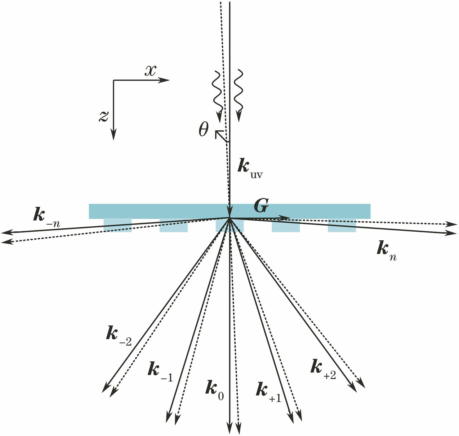
Fig. 1. Wave vectors of incident and diffracted beams
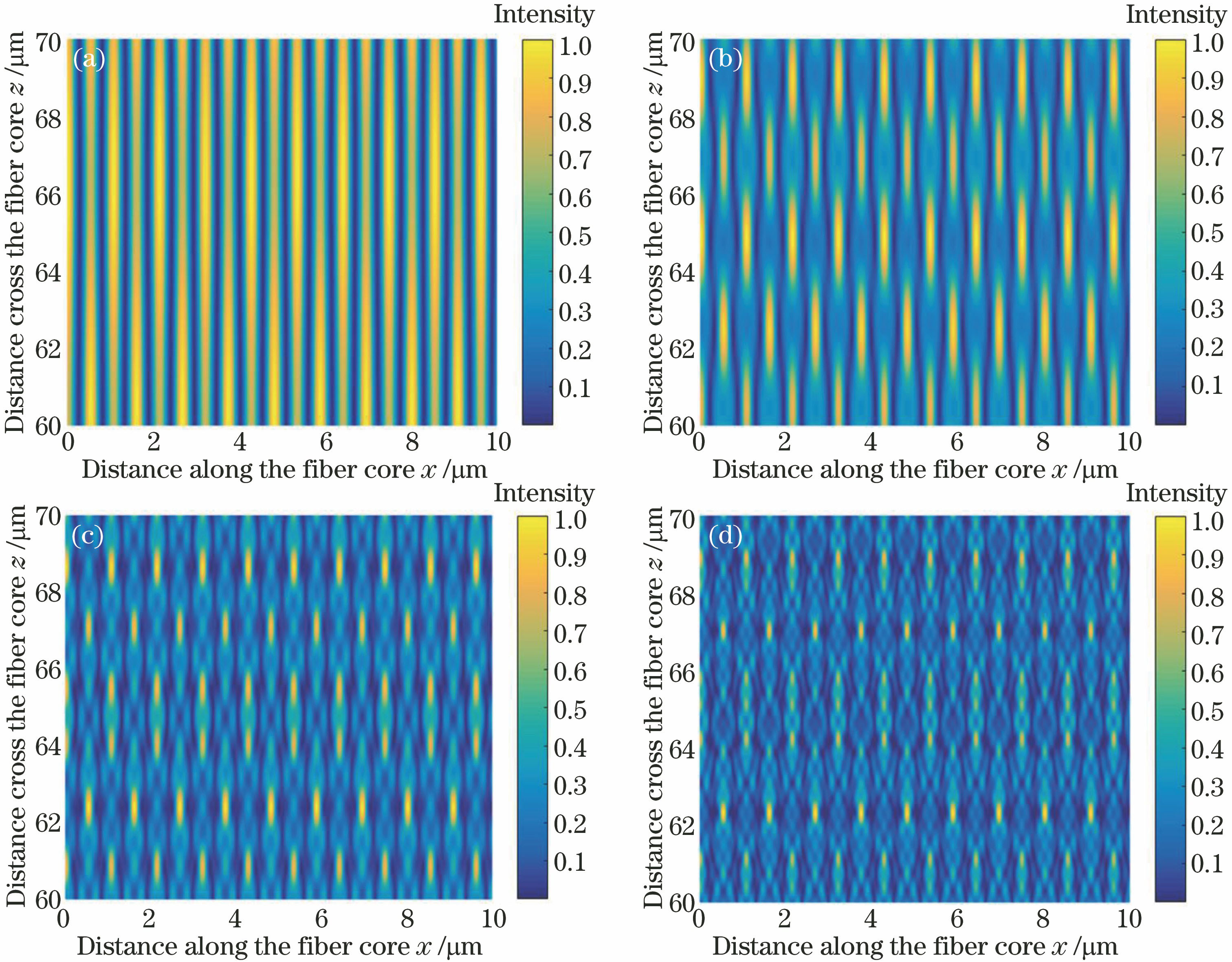
Fig. 2. Intensity distribution produced inside the fiber core region during FBG fabrication using the phase mask technique. (a) ±1 and 0 diffraction orders; (b)±2, ±1 and 0 diffraction orders; (c)±3, ±2, ±1 and 0 diffraction orders; (d)±4, ±3, ±2, ±1 and 0 diffraction orders
Fig. 3. Spatial spectra of the interfering light field over a fiber core mode field with a diameter of 10 μm. (a) ±1 and 0 diffraction orders; (b)±2, ±1 and 0 diffraction orders; (c)±3, ±2, ±1 and 0 diffraction orders; (d)±4, ±3, ±2, ±1 and 0 diffraction orders
Fig. 4. Microscopic image of FBG in 10/130 μm fiber
Fig. 5. Phase mask interference field contrast and refractive index modulation depth in FBGs as a function of the distance between the phase mask and the fiber core
Fig. 6. Loss of FBGs with the same reflectivity as a function of refractive index modulation depth in FBGs
Fig. 7. Phase mask interference field contrast as a function of the diffraction efficiency of 0 order diffracted light
Fig. 8. Spatial spectra of the interfering light field over a fiber core mode field diameter of 10 μm considering the ±4, ±3, ±2, ±1 and 0 diffraction orders. (a) z=100-110 μm; (b) z=1000-1010 μm; (c) z=2000-2010 μm
Fig. 9. Interference distance of ±1 order diffraction lights on z axis varied with incident angle of UV light
|
Table 1. Diffraction efficiency of phase mask

Set citation alerts for the article
Please enter your email address
© Copyright 2018-2021 | Chinese Laser Press. All Rights Reserved 沪ICP备15018463号-20