
Yonatan Stern, Kun Zhong, Thomas Schneider, Ru Zhang, Yossef Ben-Ezra, Moshe Tur, and Avi Zadok. Tunable sharp and highly selective microwave-photonic band-pass filters based on stimulated Brillouin scattering[J]. Photonics Research, 2014, 2(4): B18
- Photonics Research
- Vol. 2, Issue 4, B18 (2014)
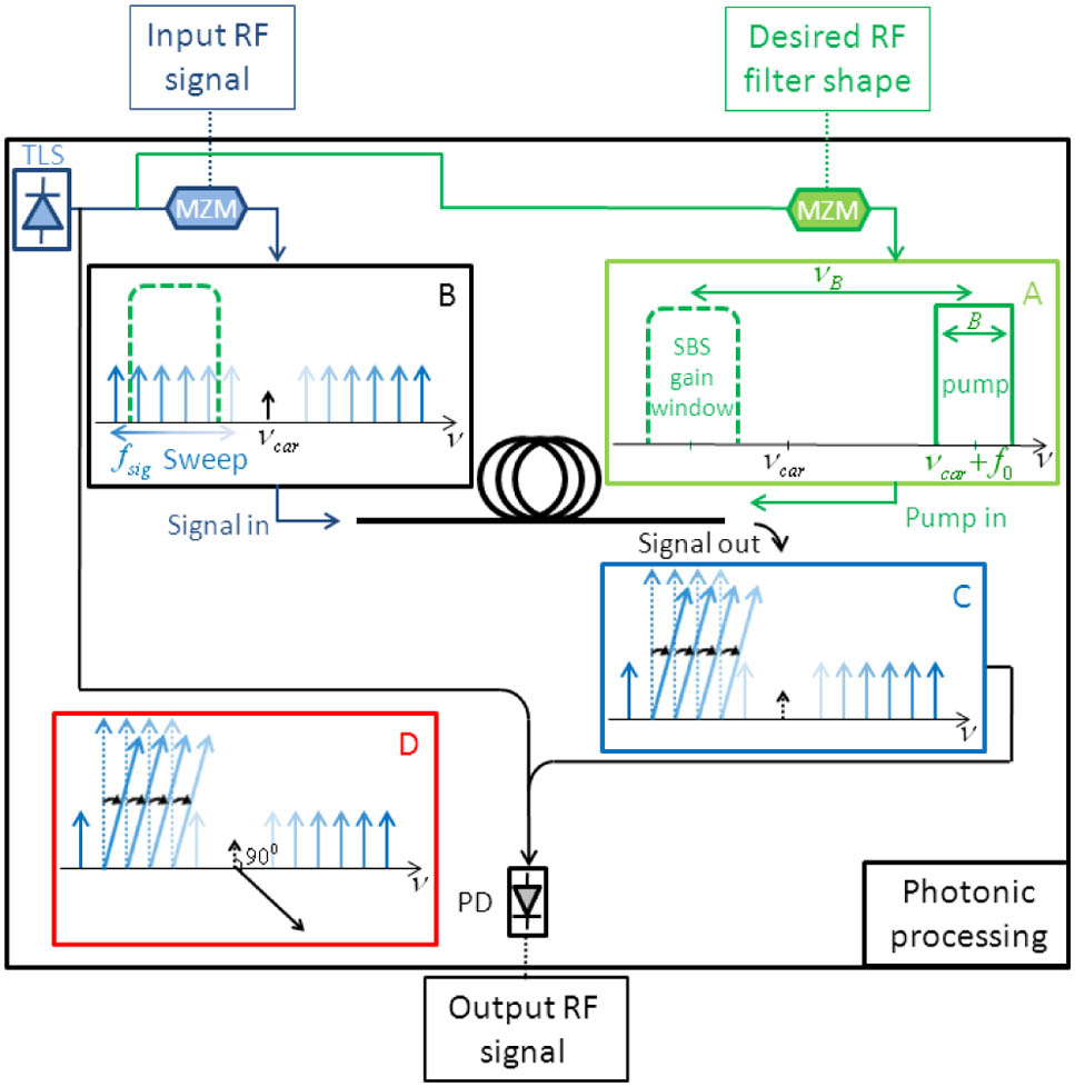
Fig. 1. Schematic illustration of the working principle of polarization-enhanced, SBS-based MWP BPFs. f sig
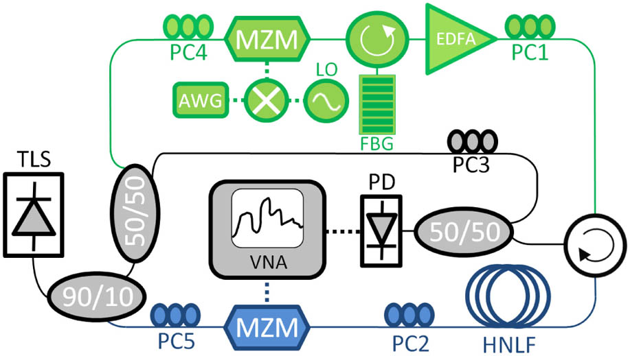
Fig. 2. Experimental setup for the demonstration of SBS-based, polarization-enhanced MWP BPFs. FBG, fiber Bragg grating.
Fig. 3. Experimentally obtained frequency response of a 500-MHz-wide, polarization-enhanced, SBS-based MWP BPF (black solid) and the corresponding simulated response (red-dashed). The latter is based on measurements of the broadened pump PSD.
Fig. 4. Normalized frequency responses of 500-MHz-wide MWP BPFs, with central frequencies of 1.65 GHz (green), 1.9 GHz (red), and 2.15 GHz (blue).
Fig. 5. Normalized frequency responses of MWP BPFs, obtained using pump bandwidths of 250 MHz (blue), 500 MHz (red), and 1 GHz (green).
Fig. 6. Examples of normalized frequency responses of MWP filters with various magnitude transfer functions.
Fig. 7. Selectivity of a 500-MHz-wide MWP BPF as a function of the SBS pump power. The input optical power of the signal sideband was − 32 dBm
Fig. 8. SNR of a RF tone at the output of a 500-MHz-wide, MWP BPF as a function of the SBS pump power. The inset shows an example of the RF PSD at the filter output, obtained for an input CW at 1.9 GHz and pump power 20.8 dBm. A pedestal of RF noise due to SBS-ASE, spanning the entire filter passband, restricts the output SNR to 14.8 dB in this particular measurement.
Fig. 9. LDR measurement: output electrical power of an amplified CW RF signal, as a function of the optical power of the input signal sideband.

Set citation alerts for the article
Please enter your email address
© Copyright 2018-2021 | Chinese Laser Press. All Rights Reserved 沪ICP备15018463号-20