


Zhao Haiyang, Li Xinmei, Lu Caibin. Microstructure and Properties of Laser Cladding Ni-Al/Al2O3-13%TiO2 Cermet Coating[J]. Laser & Optoelectronics Progress, 2020, 57(21): 211406
- Laser & Optoelectronics Progress
- Vol. 57, Issue 21, 211406 (2020)
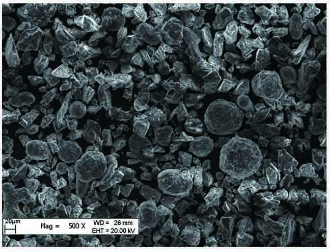
Fig. 1. Morphology of Ni-Al/Al2O3-13%TiO2 cermet composite cladding powder
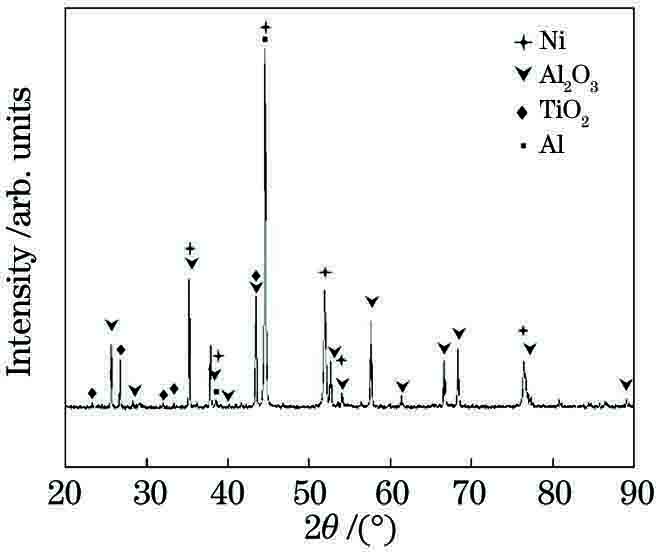
Fig. 2. XRD of Ni-Al/Al2O3-13%TiO2 cermet composite cladding powder
Fig. 3. Test results. (a) Cladding layer width and thickness change with scanning speed; (b) cladding layer depth, height, and dilution rate change with scanning speed
Fig. 4. Macroscopic morphology of Ni-Al-AT13 coating cross section
Fig. 5. Test results. (a) Cladding layer width and thickness change with laser power; (b) cladding layer depth, height, and dilution rate change with laser power
Fig. 6. Coating morphology. (a) Ni-Al coating morphology; (b) Ni-Al-AT13 coating morphology
Fig. 7. Test results. (a)-(c) Ni-Al cladding layer bottom, middle, and near surface; (d)-(f) Ni-Al-AT13 bottom, middle, and near-surface layer
Fig. 8. XRD pattern of NiAl coating
Fig. 9. XRD pattern of NiAl/AT13 composite coating
Fig. 10. Microhardness distribution of Ni-Al/Ni-Al-AT13
Fig. 11. Wear volume of substrate and cladding
Fig. 12. Wear morphology. (a) 45 steel substrate; (b) Ni-Al coating; (c) Ni-Al-AT13 cermet composite coating
|
Table 1. Effect of scanning speed on surface morphology of cladding
|
Table 2. Effect of laser power on surface morphology of coating

Set citation alerts for the article
Please enter your email address
© Copyright 2018-2021 | Chinese Laser Press. All Rights Reserved 沪ICP备15018463号-20