Precise and ultrafast control over photo-induced charge currents across nanoscale interfaces could lead to important applications in energy harvesting, ultrafast electronics, and coherent terahertz sources. Recent studies have shown that several relativistic mechanisms, including inverse spin-Hall effect, inverse Rashba–Edelstein effect, and inverse spin-orbit-torque effect, can convert longitudinally injected spin-polarized currents from magnetic materials to transverse charge currents, thereby harnessing these currents for terahertz generation. However, these mechanisms typically require external magnetic fields and exhibit limitations in terms of spin-polarization rates and efficiencies of relativistic spin-to-charge conversion. We present a nonrelativistic and nonmagnetic mechanism that directly utilizes the photoexcited high-density charge currents across the interface. We demonstrate that the electrical anisotropy of conductive oxides RuO2 and IrO2 can effectively deflect injected charge currents to the transverse direction, resulting in efficient and broadband terahertz radiation. Importantly, this mechanism has the potential to offer much higher conversion efficiency compared to previous methods, as conductive materials with large electrical anisotropy are readily available, whereas further increasing the spin-Hall angle of heavy-metal materials would be challenging. Our findings offer exciting possibilities for directly utilizing these photoexcited high-density currents across metallic interfaces for ultrafast electronics and terahertz spectroscopy.
Precise control of charge-carrier transport across nanoscale interfaces at ultrafast speeds is essential for the advancement of various modern technologies, including solar cells,1 photosynthesis,2 and high-efficiency optoelectronic devices.3 Recent studies have shown that when metallic interfaces are excited by strong femtosecond laser pulses, enormous current density exceeding can be produced,4,5 which is several orders of magnitude higher than those typically used in electronic devices. If harnessed, these high-frequency and high-density charge currents could revolutionize the field of ultrafast electronics6 and also lead to the development of bright and coherent terahertz sources.7 However, due to the nanometer scale and localization of the generated currents around the buried interface, collecting their radiation energy poses a significant challenge.
Recently, Kampfrath et al. demonstrated a promising approach for utilizing the enormous charge currents for generation of strong and broadband terahertz radiation.7–9 This approach involves a heterostructure consisting of a thin heavy-metal (HM) film, such as Pt, and a thin ferromagnetic (FM) film, where longitudinal spin-polarized currents injected from the FM layer can be deflected to transverse charge currents in the HM layer via the relativistic inverse spin-Hall effect (ISHE). In this context, longitudinal currents are defined as those flowing perpendicular to the interface. Recently, metasurface-structured devices have also been demonstrated for the simultaneous generation and manipulation of terahertz waveforms.10,11 Moreover, this concept has attracted great interest because it provides an all-optical, contact-free method for probing the transient state of magnetism with subpicosecond time resolution in FM materials,12–14 antiferromagnetic materials,15 and for reliably measuring the spin-Hall angle of HM materials.16 Later, other relativistic mechanisms, including the inverse Rashba–Edelstein effect17,18 and the inverse spin-orbit-torque effect,19 were also found capable of terahertz-wave generation, with the former having comparable efficiency with the ISHE, and with the latter effect being much weaker.
All the current-deflection mechanisms described above rely on a two-step process involving generation of spin-polarized currents and relativistic spin-to-charge conversion. The spin-polarized currents are typically extracted from the laser-induced charge currents through superdiffusive spin scattering,20,21 resulting in a spin polarization rate of 0.2 to 0.4 within the spin diffusion length.22,23 As a result, an external magnetic field is usually required to saturate the magnetization of the FM materials, although field-free emitters have recently been realized by utilizing exchange bias between antiferromagnetic and FM nanofilms.24 In the second step, the efficiency of the relativistic spin-to-charge conversion is characterized by the spin-Hall angle . For Pt, which is known for its strong spin–orbit coupling, is typically around 0.1,19 while the conversion efficiency of an AgBi interface is estimated to be between 0.064 and 0.16.18 Consequently, the ability to fully utilize the interface transient currents is hindered by the low conversion efficiencies in these two steps. The conversion efficiency could be significantly improved if one could directly and efficiently control the laser-induced charge currents across the interface, rather than relying on spin-polarized currents.
Sign up for Advanced Photonics TOC. Get the latest issue of Advanced Photonics delivered right to you!Sign up now
In this work, we report a nonrelativistic and nonmagnetic mechanism for direct conversion of laser-excited high-density longitudinal charge currents to transverse ones, leading to efficient terahertz-wave generation without the need for external fields. The generation process is initiated by the superdiffusive charge current injected from the adjacency of an optically excited metal thin film, which is then deflected from the longitudinally injected direction to the transverse direction by the anisotropic electrical conductivity of the conductive rutile oxides and . Notably, was recently found to be an itinerant antiferromagnetic material25,26 that has attracted enormous interest in magneto-electronic research,27–33 whereas is nonmagnetic.34 Our results show that the terahertz emission is highly sensitive to the crystal orientation but not influenced by the polarization of the excitation laser. This distinguishes our mechanism from the aforementioned magnetic near-infrared (NIR)-to-terahertz conversion mechanisms4,17–19 that rely on relativistic spin–orbit coupling, as well as from other nonmagnetic mechanisms, such as optical rectification35,36 or difference-frequency generation,37,38 which requires coherent wave mixing of the excitation laser. The conversion efficiency of the sample matches that of the ISHE, and this mechanism can potentially further improve efficiency by implementing conductive materials with stronger electrical anisotropy. These findings open up possibilities to directly harness interface high-density charge currents for ultrafast electronics and terahertz spectroscopy.
2 Results
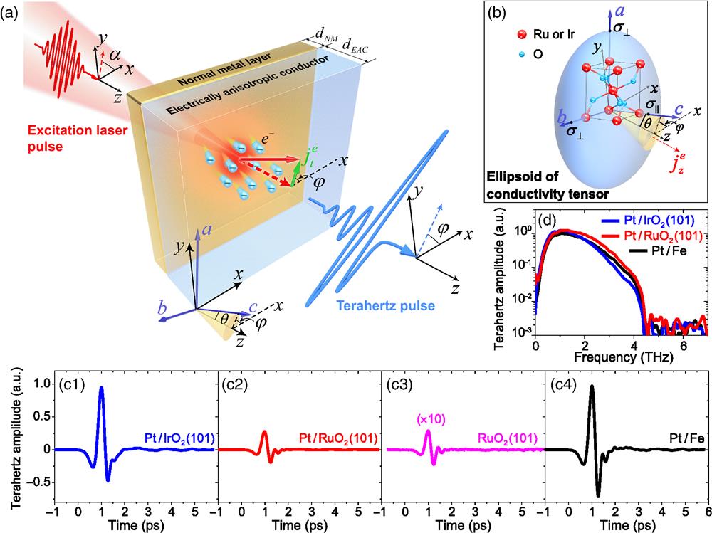
Figure 1(a) illustrates the schematic of the experimental setup. The device is based on a heterostructure composed of a single-crystal film of either or and a nonmagnetic metal (NM) thin film, both of which are nanometers thick. Several different metals (Cu, Pt, W, and Ir) were used for the NM layer. The and films are both conductive rutile oxide belonging to the space group P42/mnm with unequal lattice parameters [, see Fig. 1(b)]. As a result, they are both electrically anisotropic conductors (EACs) with , where and are the conductivity along the axis and that in the plane, respectively. The single-crystal RuO or film was deposited on the or substrates and then capped by an NM film. See Appendix A and Sec. S1 in the Supplementary Material for the details of sample preparation and basic characterizations.
Figure 1.Experimental setup and terahertz signals. (a) Schematic of the experimental setup. The coordinates are adapted to the laboratory frame and the lattice coordinates are labeled as . The crystal azimuthal angle , polar angle and the laser-polarization angle are defined. Femtosecond-laser-induced electrons are injected from the NM layer, resulting in transient electron currents along . In the experiment, the excitation pulse is primarily incident from the EAC layer side. However, for ease of illustration, it is depicted as incident from the NM layer side. Owing to the electrical anisotropy in the EAC layer, transverse electron currents () are generated flowing at an angle of relative to the axis. Inset: illustration of superdiffusive electron currents induced by laser-pulse excitation. (b) Schematic of the ellipsoid of conductivity tensor of and in the laboratory frame, displaying anisotropy in electrical conductivities (). The schematic uses the same coordinate and angle definitions as described in panel (a). (c) Terahertz waveforms generated from (c1) , (c2) , (c3) , and (c4) Pt/Fe devices. The signal from the thin film is scaled 10 times for comparison. (d) Terahertz spectra obtained via fast Fourier transform (FFT) of the waveforms in panel (c).
In our experiment, the NM/EAC heterostructure is excited by femtosecond pulses (duration of , center wavelength 1030 nm, repetition rate 100 kHz). The excitation laser pulses are generated through high-quality pulse compression enabled by solitary beam propagation in periodic layered Kerr media.39,40 The laser beam is incident normally from the substrate side onto the heterostructure along the direction, and the beam radius is focused to around 0.7 mm on the sample. The coordinates refer to the laboratory frame, while , , and are the crystallographic axes. The polarization of the excitation laser can be adjusted with a combination of wave plates to be either linearly polarized with a polarization angle in the plane or to be circularly polarized. The sample temperature can be changed between 77 and 500 K. In the experiment, the orientation of the or crystals is varied by growing the sample on different substrates or by rotating the sample in-plane around . Hence, we define the polar angle between the crystal axis and the axis, and the azimuthal angle between the projection of the axis in the plane and the axis [see Figs. 1(a) and 1(b)]. Finally, the emitted terahertz waveforms are detected using a polarization- and time-resolved terahertz spectroscopy setup based on electro-optic sampling (EOS).41–43 The waveforms of the two orthogonal terahertz polarizations ( and ) can be resolved (see Appendix A).
Figure 1(b) presents the terahertz waveforms generated at room temperature by a (10 nm) thin film, Pt (2 nm)/ (10 nm), and Pt (2 nm)/ (10 nm) heterostructures, in comparison with a spintronic terahertz emitter composed of a Pt (2 nm)/Fe (2 nm) heterostructure whose conversion efficiency has been optimized.9 The signal from the spintronic emitter was measured under an external magnetic field that magnetizes the FM layer, while those from the thin film and from the NM/EAC heterostructures were measured without any external fields. In this measurement, the and films are both (101)-oriented and are grown on the substrates.
First of all, we find that capping with a 2 nm Pt layer enhances the emitted terahertz amplitude by a factor of 10, indicating the strong influence of the heterostructure on the NIR-to-terahertz conversion. The heterostructure can deliver terahertz amplitude about 3 times as strong as . Remarkably, the terahertz emission from is almost as strong as that from Pt/Fe, indicating high conversion efficiency. The strength of this terahertz signal is comparable to those generated by several commercial terahertz sources based on nonlinear optical crystals and photoconductive switches.7,9,11 We also find that the terahertz spectra of different samples are almost identical, as shown in Fig. 1(c).
Previous studies have shown that the ISHE in the NM layer can cause deflection of spin-polarized currents, leading to significant enhancement of terahertz generation in heterostructures, such as those involving a laser-excited FM layer4,7–9 and a ferrimagnetic yttrium iron garnet layer driven by the spin-Seebeck effect12 or an antiferromagnetic NiO layer with coherently excited spin currents.15 The polarity and amplitude of the emitted terahertz field are dependent on the spin-Hall angle () of the NM material. In Fig. 2(a), we investigate the influence of different NM materials on terahertz emission from NM/EAC heterostructures. The terahertz-wave amplitudes, the spin-Hall angles (), and the optical absorption coefficients (OACs) of different NM materials are summarized in Fig. 2(b). Here the most important observation is that the terahertz-wave polarity from the heterostructure is not reversed, despite of being of opposite sign compared to that of Pt.7 This behavior contrasts with the spintronic emitter (see Sec. S2 in the Supplementary Material). Further, we find that even though Cu has a small spin-Hall angle, the terahertz amplitude from is comparable to that from [Fig. 2(b)]. These results therefore clearly distinguish the conversion mechanism of the NM/EAC heterostructures from ISHE.
Figure 2.Effect of NM materials and laser polarization states. (a) Terahertz waveforms generated by devices with NM materials of Ir, Cu, W, and Pt. The thickness of the NM layer is 2 nm. (b) Terahertz signal amplitude as a function of the NM materials used for the devices (red bars). For comparison, OACs at the laser wavelength of (blue bars) and spin-Hall angles (green bars) of the respective NM materials are also shown. (c) Terahertz signal amplitudes of the and components from the device as a function of the polarization angle of the linearly polarized excitation laser. Inset: projection of the terahertz waves for different values of . (d) Terahertz waveforms from the device excited by excitation pulses with linear, right- and left-circular polarizations.
In Figs. 2(c) and 2(d), the dependence of terahertz emission on the polarization states of the excitation laser is further investigated. The crystal used in this measurement is (101) oriented with its axis fixed in the plane at [Fig. 1(a)]. The results show that the emitted terahertz wave maintains a constant field amplitude and linear polarization along , when the polarization angle () of the linearly polarized excitation laser is varied [Fig. 2(c)]. Note that this result is obtained after correcting for the birefringent effect of the substrate. The polarization-independent result is further confirmed by samples grown on the substrate, where the optical birefringent effect is not present (see Sec. S4 in the Supplementary Material). The projections of the terahertz waves under different are shown in the inset of Fig. 2(c). Furthermore, there is almost no difference in the amplitudes or waveforms of the terahertz signals excited by linearly and circularly polarized laser pulses [Fig. 2(d)]. Similar results can be obtained from the heterostructures (see Sec. S8 in the Supplementary Material), leading to the conclusion that the terahertz generation from the NM/EAC emitters is not affected by the polarization of the excitation laser.
It should be noted that the independence of terahertz emission on the excitation-laser polarization rules out optical rectification35,36 in the or crystals as the mechanism for the NIR-to-terahertz conversion. This result is also distinct from the recent Pt/NiO emitter,15 where the coherent spin-current generation in NiO depends strongly on the laser polarization. Instead, the polarization independence here is in line with the spintronic emitters, where the terahertz emission is initiated by the incoherent conversion of optical energy to charge/spin currents.4,7 This is further supported by the almost identical terahertz spectra from the two different types of emitters [see Fig. 1(c)], indicating similar carrier dynamics.
Nonetheless, our results strongly indicate that the efficient NIR-to-terahertz conversion in the NM/EAC heterostructures is nonmagnetic in origin. First, ISHE has been excluded. We also find that the emitted terahertz waves are unaffected by external magnetic fields (see Sec. S5 in the Supplementary Material). Second, while is an itinerant antiferromagnetic material,25,26 is known to be nonmagnetic.34 Nonetheless, the emission properties from the two heterostructures are very similar (see Sec. S8 in the Supplementary Material). Third, the temperature-dependent results show that the terahertz-wave amplitude from increases monotonically up to 500 K (see Sec. S6 in the Supplementary Material), which is higher than the reported Néel temperature of thin films.26
Since the OACs of and are more than 1 order of magnitude smaller than that of the NM materials at the wavelength of ,44 we believe that the terahertz emission originates from the injection of charge currents from the optically excited NM layer into the or crystals [see inset of Fig. 1(a)]. This is supported by the fact that the general trend of the terahertz amplitude versus NM materials is in semiquantitative agreement with the OACs of the NM materials [Fig. 2(b)]. Here our results also suggest that the thermally driven Seebeck effect is unlikely to be responsible for the charge-current injection. This is because the terahertz waveforms emitted from devices with different NM materials are almost identical (see Fig. S2c in the Supplementary Material), whereas distinctive temperature dynamics would be expected in these metals after laser-pulse excitation (see Sec. S3 in the Supplementary Material). Instead, we believe that the dominant contribution to the interfacial charge currents comes from the superdiffusive transport of the photoexcited high-energy electrons20,21 prior to the thermalization process.
The observation of the -polarized terahertz field indicates the existence of a transverse charge current flowing along the direction in our experimental setup [Fig. 1(a)]. We find that this can be attributed to the anisotropic electrical conductivity of single-crystal and . Due to the unequal lattice parameters, the second-rank conductivity tensor is given by in the crystal coordinate (), where . By rotating the crystal under the azimuth angle and the polar angle , off-diagonal tensor components appear in the laboratory coordinate: and , and the diagonal component becomes (see Appendix B). As a result, when the charge current () is injected along (electron current along ), the conductivity anisotropy leads to the transverse charge current density of and , where the coefficient of conductivity anisotropy is given by when . The amplitude of the -polarized terahertz field is proportional to the transverse currents .
The above theory is confirmed by the experimental measurements under different crystal orientations [(101), (110), (100), and (001)], as shown in Fig. 3(a). We find that only when the crystal orientation is (101) with can strong terahertz emission be observed, and for , only the -polarized terahertz field is observed, because and . On the other hand, when the axis is either aligned with [(001) with ] or in the plane [(100) or (110) with ], the terahertz emission in both polarizations is strongly suppressed, because under these conditions. Our results also show that when the crystal orientation is (101), the polarization of the emitted terahertz field rotates following the azimuthal angle [Fig. 3(b)]. The peak amplitudes are summarized in Fig. 3(c), and the sinusoidal behaviors of the and amplitudes are in excellent agreement with and , respectively.
Figure 3.Effect of crystal orientations. (a) and components of terahertz waveforms generated by devices with different crystal orientations and polar angles . (b) and components of terahertz waveforms generated by at different azimuthal angles while keeping fixed at 34.7 deg. (c) Terahertz signal amplitude of and components from the device at different azimuthal angles . The solid lines represent the sine and cosine fitting to the results.
The ability to convert to is characterized by of different materials, which is analogous in position to the spin-Hall angle within the ISHE formalism.4,45,46 In Table 1, we list the experimentally measured and of and , respectively (see Appendix A). When the crystal orientation is (101), we find that of is times that of . In Fig. 4(a), we show that terahertz amplitudes from the and structures both grow linearly as a function of the incident pump fluence () when . Remarkably, the slope of the linear increase of is times that of , in excellent agreement with the ratio of between the two materials. We note that, due to the low conductivity of and , the impedance shunt effect only contributes of the difference in terahertz amplitudes (see Appendix C). The NIR-to-terahertz conversion efficiency of the heterostructure almost reaches that of Pt/Fe heterostructure. More interestingly, the signal increases of these two structures both deviate from a linear increase at , while that from the structure continues to increase linearly at high pump fluence. This behavior may be attributed to the contrasting temperature-dependent behaviors of the three structures: when the laser excitation increases the sample temperature, the terahertz signal from increases monotonically with the rising sample temperature up to 500 K, whereas those from and Pt/Fe structures both decrease (see Sec. S6 in the Supplementary Material).
()
()
8.13
8.63
34.7
0.028
3.18
4.22
35.0
0.139
Table 1. Longitudinal () and transverse () conductivities, crystal polar angles , and the coefficients of electrical anisotropy of and .
Figure 4.Optimizing the conversion efficiency. (a) Terahertz signal amplitude as a function of incident laser fluence from the , , and Pt/Fe samples. The red and blue dashed lines represent the linear fits to the low-fluence experimental results of and , respectively. The slope of the red dashed line is times of that of the blue dashed line. (b) Terahertz signal amplitude as a function of thickness of the layer () of the device. (c) Terahertz signal amplitude as a function of thickness of the Pt layer () of the device. The solid lines in (b) and (c) represent a global fit using the thickness-dependent model (see Appendix C).
In Figs. 4(b) and 4(c), we plot the dependence of the terahertz amplitudes as a function of the thickness of the EAC layer () and the NM layer (), respectively. Here we take the device as an example. Importantly, we find that the terahertz amplitude gradually increases as increases from 0 and peaks at . This indicates that the deflection of the charge currents is not caused by the interface effect. In contrast, the terahertz amplitude as a function of exhibits much slower variation, and the maximum terahertz signal is generated when .
Quantitatively, when we fix the crystal orientation with and , the amplitude of the -polarized terahertz field () is directly related to the -integration of the transverse charge current density () by7where is the elementary charge. Here is the effective impedance of the heterostructure in the transverse direction shunted by the adjacent substrate and air spaces, which is related to the thickness of the EAC layer () and the NM layer () (see Appendix C). The longitudinal current density is proportional to the density of the absorbed photons: , where is the absorbed laser fluence of the NM layer and is the excitation photon energy. In addition, the spatial distribution of that contributes to the terahertz radiation is localized near the heterostructure interface, due to the finite hot-electron velocity-relaxation lengths in the EAC layer () and the NM layer () (see Appendix C). The best fits to the experimental results are shown in Figs. 4(b) and 4(c) (solid lines), which yield and for and Pt, respectively. The latter is consistent with previous work.7
3 Discussion
Our study has demonstrated a nonmagnetic and nonrelativistic mechanism for generating strong terahertz-wave emission by directly harnessing laser-excited charge currents across nanoscale interfaces. This approach utilizes the anisotropic electrical conductivity of materials and eliminates the need for conversion of charge currents to spin-polarized currents. Our results also highlight the importance of using conductive materials to enable efficient injection of laser-induced currents into the EAC layer. This is supported by the fact that the heterostructure does not generate terahertz radiation [Fig. 4(c)], although is an insulator exhibiting similar crystal anisotropy.
Compared to the ISHE mechanism, this mechanism could offer much higher conversion efficiency by selecting conductive materials with large electrical anisotropy, whereas further increasing the spin-Hall angle of HM materials would be difficult. For example, the conductivity in the basal plane of a graphite thin layer is , while that normal to the plane is .47 When charge currents are injected with an angle of to 2 deg relative to the material normal axis, the significant difference in conductivity could possibly lead to terahertz emission with an order of magnitude of higher intensity compared to that from the device in this study (see Sec. S7 in the Supplementary Material). This could potentially be achieved by implementing a spatially varying chemical vapor deposition method to create nanoscale thickness gradients48,49 in the layered materials, thereby enabling precise control over the current-injection angle . However, special care must be taken to achieve a high-quality interface between the NM and layered materials with thickness gradients to suppress interfacial scattering.50
4 Appendix A: Experimental Details
Single-crystal and films were epitaxially grown on the double-polished or substrates by dc magnetron sputtering at 500°C in a chamber with the base pressure better than . Both and substrates were preannealed at 500°C for 1 h before sample growth. Both and films were grown by reaction sputtering in the mixed atmosphere of Ar and with the ratio of 4:1. The normal metals Pt, W, and Cu were deposited by dc magnetron sputtering at room temperature.
In the terahertz experiment, we excited the sample with femtosecond pulses (duration, 25 fs; center wavelength, 1030 nm; pulse energy, ; repetition rate, 100 kHz; and beam radius at the sample, 0.7 mm) under normal incidence from the substrate side. The terahertz electric field was subsequently detected by EOS using a -thick (110)-oriented GaP crystal, with the two orthogonal components ( and ) resolved using a broadband wire-grid polarizer. All the measurements were performed in a dry air atmosphere. The details of the polarization-resolved EOS setup can be found elsewhere.11
For the electrical measurements, the single-crystal and films were patterned into devices with two orthogonal Hall bars through standard photolithography and Ar-ion etching. The current can flow through either the crystal axis or axis. The width and the distance between the two electrodes of the Hall bars are 150 and , respectively. The electrical measurements were carried out on a cryogenic probe station (LakeShore EMPX-HF) at room temperature. A dc current of 1 mA was injected into the longitudinal bar, and the voltage was detected by a Keithley 2182A nanovoltmeter.
Both and are rutile oxides with the P42/mnm space group, where Ru/Ir atoms occupy the center of stretched oxygen octahedrons. The conductivity tensor in the crystal coordinate that satisfies the requirements of symmetric transformation is given by
In the laboratory frame (), the crystal orientation is defined by the azimuthal angle and the polar angle . The conductivity tensor in the coordinate is given by
As a result, when charge currents are injected along the direction [electron currents along in Fig. 1(a)], transverse currents along the - and -directions can be induced, with the conversion efficiency characterized by . When , we obtain .
6 Appendix C: Model for Thickness Dependence of Terahertz Amplitude
To model the terahertz emission amplitude of the NM/EAC bilayer, we make use of Eq. (1). The impedance of the bilayer is given by where is the terahertz frequency, is the vacuum impedance, is the total thickness of the heterostructure, is the space-dependent sample conductivity, and and are the refractive indices at the terahertz frequency of air and , respectively. As noted in Ref. 7, after excitation by the pump pulse, the terahertz signal is only contributed by the hot electrons injected from the NM layer that fall within the electron diffusion length of the EAC layer, . Similarly, only excited electrons within the diffusion length of the NM layer, , are able to propagate through the interface without scattering. As a result, the terahertz radiation is caused by the charge currents localized near the interface of the heterostructure.
Following the above assumptions and the formalism in Ref. 51, we obtain the spatial distribution of the ballistic charge current density inside the EAC layer by and the injected charge current density is proportional to the integration of the photoexcited hot electron density over the NM layer by considering ,
By inserting Eqs. (4)–(6) into Eq. (1), we obtain with the two diffusion lengths ( and ) and a global amplitude being the only free parameters. Here considers only the absorbed fluence by the NM layer, which is also thickness-dependent by considering the reflection and absorption loss on the EAC layer and the NM layer, where and are the reflectivity of the EAC–air interface and the EAC–NM interface, respectively. and are the OACs of the NM and the EAC materials, respectively. Most of the optical and electrical parameters in the model can be determined by the literature values (see Sec. S3 in the Supplementary Material) or by experimental measurements, leaving the hot-electron velocity relaxation lengths7 ( and ) and a global amplitude as the only free parameters. The fitting to the experimental results in Figs. 4(b) and 4(c) yields for Pt and for . The former is consistent with previous work.7
Chuanshan Tian is a professor in the Department of Physics and State Key Laboratory of Surface Physics, Fudan University. His research group has long been committed to the experimental exploration of surface and interface physical and chemical phenomena, with a special focus on developing advanced nonlinear spectroscopy techniques to solve molecular and electronic structures at interfaces related to renewable energy and environmental issues.
Zhe Yuan is a professor in the Institute for Nanoelectronic Devices and Quantum Computing, Fudan University. His research interests are mainly focused on spintronics theory and first-principles calculations, including spin transport and dynamics, magnetic materials, and the neuromorphic computing algorithms implemented using spintronic devices.
Lei Zhou is “XiDe” chair professor and head of the Department of Physics at Fudan University. His main research focuses on the field of nano-optics. In 2019, he was elected as a fellow of the Optical Society of America, and won the second prize of Chinese National Natural Science Award. He is the founding editor-in-chief of Photonics Insights, managing editor of Nanophotonics, and serves on editorial boards for Physical Review Materials and Opto-Electronic Science.
Yizheng Wu has been a professor in the Department of Physics and State Key Laboratory of Surface Physics, Fudan University, since 2005. His research interests span multiple branches of magnetism and spintronics, including thin film magnetism, antiferromagnetic spintronics, spintronics terahertz emission, and spin-correlated transport in single crystal systems.
Zhensheng Tao has been a professor in the Department of Physics and State Key Laboratory of Surface Physics, Fudan University since 2018. His research activities are devoted to the experimental study of ultrafast optics and condensed matter physics, with a particular focus on the study of ultrafast non-equilibrium light-matter interactions and the development of ultrafast optical technologies.