• Photonics Research
  • Vol. 9, Issue 11, 2265 (2021)
Chao Wu1、2、3、*, Quan Li1、2、4, Zhihui Zhang1、2, Song Zhao1、2, and Hongqiang Li1、2、3、5
Author Affiliations
  • 1School of Physics Science and Engineering, Tongji University, Shanghai 200092, China
  • 2Shanghai Key Laboratory of Special Artificial Microstructure Materials and Technology, Tongji University, Shanghai 200092, China
  • 3The Institute of Dongguan-Tongji University, Dongguan 523808, China
  • 4College of Electronic and Information Engineering, Tongji University, Shanghai 200092, China
  • 5e-mail: hqlee@tongji.edu.cn
  • show less
    DOI: 10.1364/PRJ.440166 Cite this Article Set citation alerts
    Chao Wu, Quan Li, Zhihui Zhang, Song Zhao, Hongqiang Li. Control of phase, polarization, and amplitude based on geometric phase in a racemic helix array[J]. Photonics Research, 2021, 9(11): 2265 Copy Citation Text show less
    (a) Schematic of a unit cell of the racemic metallic helix array. (b) Top view of the unit cell.
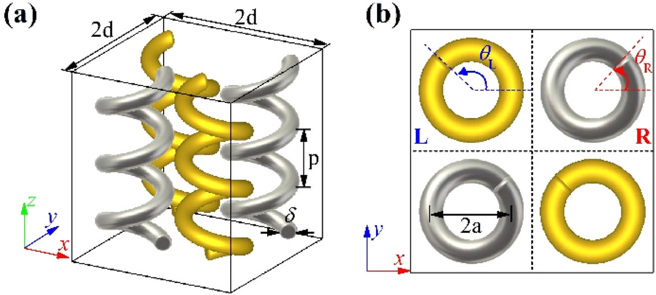
    Fig. 1. (a) Schematic of a unit cell of the racemic metallic helix array. (b) Top view of the unit cell.
    (a) Schematic of a unit cell of the 0° oriented RH subarray. (b) Calculated (lines) and measured (circles) reflection spectra of the 0° oriented RH subarray in circular basis. The first and the second subscripts of reflection spectra refer to the polarization states of the reflected and the incident waves, respectively. The reflection spectra are normalized to the power of incidence. (c) Reflection spectra of the RH subarray in its eigen-polarization basis. The calculated (d) tilt angles and (e) ellipticity angles of the RH and LH subarrays with orientation angles of 0°. (f) Reflection phase of states A and A* from the RH and LH subarray, respectively. The circles in (c) and (d) show the corresponding results of the eigen-polarization basis calculated from experimentally measured reflection spectra.
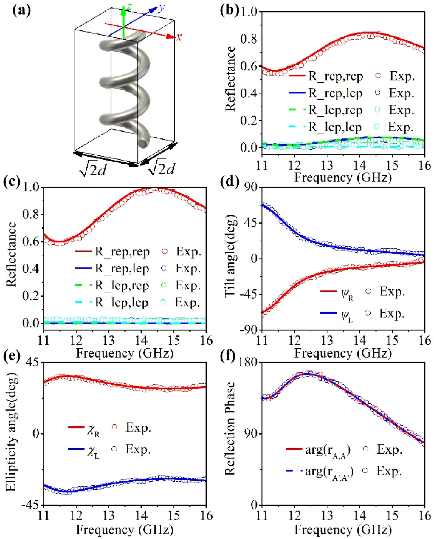
    Fig. 2. (a) Schematic of a unit cell of the 0° oriented RH subarray. (b) Calculated (lines) and measured (circles) reflection spectra of the 0° oriented RH subarray in circular basis. The first and the second subscripts of reflection spectra refer to the polarization states of the reflected and the incident waves, respectively. The reflection spectra are normalized to the power of incidence. (c) Reflection spectra of the RH subarray in its eigen-polarization basis. The calculated (d) tilt angles and (e) ellipticity angles of the RH and LH subarrays with orientation angles of 0°. (f) Reflection phase of states A and A* from the RH and LH subarray, respectively. The circles in (c) and (d) show the corresponding results of the eigen-polarization basis calculated from experimentally measured reflection spectra.
    (a) Reflection spectra of a racemic array with both RH and LH helices’ orientation angles being 0°; (b) reflectance and (c) reflection phase responses as functions of parameter α at 14.4 GHz (the parameter β is fixed to be 0°); (d) reflection phase shift of x and y polarizations as functions of parameter α, compared to the reflection phase of x polarization for a racemic array with both parameters α and β being 0°; (e) polarization evolution paths of x polarization on the Poincaré sphere; (f) the reflection phase difference Δϕ=ϕy,y−ϕx,x as functions of parameter α. The theoretical results in (d) and (f) are obtained from Eqs. (2) and (3) with ψ=0° and χ=22.5°. Circles in Fig. 3 show the corresponding measured results.
    Fig. 3. (a) Reflection spectra of a racemic array with both RH and LH helices’ orientation angles being 0°; (b) reflectance and (c) reflection phase responses as functions of parameter α at 14.4 GHz (the parameter β is fixed to be 0°); (d) reflection phase shift of x and y polarizations as functions of parameter α, compared to the reflection phase of x polarization for a racemic array with both parameters α and β being 0°; (e) polarization evolution paths of x polarization on the Poincaré sphere; (f) the reflection phase difference Δϕ=ϕy,yϕx,x as functions of parameter α. The theoretical results in (d) and (f) are obtained from Eqs. (2) and (3) with ψ=0° and χ=22.5°. Circles in Fig. 3 show the corresponding measured results.
    (a) Photograph of the device for generating vortex beam with topological charge l=1; (b) enlarged view of a unit cell; (c), (d) calculated and (e), (f) measured electric field amplitude and phase distribution of the vortex beam with topological charge l=1 at 14.4 GHz on the transverse plane 100 mm away from the device surface. The electric field distributions are normalized to the global maximum.
    Fig. 4. (a) Photograph of the device for generating vortex beam with topological charge l=1; (b) enlarged view of a unit cell; (c), (d) calculated and (e), (f) measured electric field amplitude and phase distribution of the vortex beam with topological charge l=1 at 14.4 GHz on the transverse plane 100 mm away from the device surface. The electric field distributions are normalized to the global maximum.
    Reflection spectra of racemic helix array samples as a reflective half-wave plate. Reflection spectra are calculated and measured for two samples with parameter β of (a), (b) 45° and (c), (d) 22.5°. The parameter α for both samples is 0°. The symbol 45 or −45 denotes linear polarization with a polarization angle of 45° or −45° about the x axis. The reflection spectra are normalized to the power of incidence.
    Fig. 5. Reflection spectra of racemic helix array samples as a reflective half-wave plate. Reflection spectra are calculated and measured for two samples with parameter β of (a), (b) 45° and (c), (d) 22.5°. The parameter α for both samples is 0°. The symbol 45 or 45 denotes linear polarization with a polarization angle of 45° or 45° about the x axis. The reflection spectra are normalized to the power of incidence.
    (a), (b) Reflection spectra of racemic helix array sample as a reflective quarter-wave plate. The parameters α, β of the sample are both 45°. (c), (d) Theoretical and (e), (f) calculated tilt angles ψ′ and ellipticity angles χ′ of the reflected waves under RCP incidence as functions of parameters α and β. The theoretical results are obtained from Eqs. (2)–(4) with ψ=0° and χ=22.5°. (g), (h) Reflection spectra of the racemic helix array sample that converts circular polarization states to elliptical polarization states. The parameters α, β of the sample are 12° and 15°, respectively. The tilt angle and ellipticity angle of polarization state γ are 60° and 22.865°, respectively. State γ′ is orthogonal to γ, and its tilt angle and ellipticity angle are 150° and −22.865°.
    Fig. 6. (a), (b) Reflection spectra of racemic helix array sample as a reflective quarter-wave plate. The parameters α, β of the sample are both 45°. (c), (d) Theoretical and (e), (f) calculated tilt angles ψ and ellipticity angles χ of the reflected waves under RCP incidence as functions of parameters α and β. The theoretical results are obtained from Eqs. (2)–(4) with ψ=0° and χ=22.5°. (g), (h) Reflection spectra of the racemic helix array sample that converts circular polarization states to elliptical polarization states. The parameters α, β of the sample are 12° and 15°, respectively. The tilt angle and ellipticity angle of polarization state γ are 60° and 22.865°, respectively. State γ is orthogonal to γ, and its tilt angle and ellipticity angle are 150° and 22.865°.
    (a) Calculated reflection amplitude of the x-to-y polarization conversion component for a racemic helix array with β=0°, 15°, 30°, and 45°. The parameter α is fixed to be 0°. (b) Reflection amplitude (blue squares) and phase (black circles) of the x-to-y polarization conversion component as a function of parameter β at 14.4 GHz. Theoretical and calculated (c), (e) amplitude and (d), (f) phase of the reflected co-polarized components under x-polarized incidence as a function of parameters α and β at 14.4 GHz. The theoretical results are obtained from Eqs. (1) and (2) with ψ=0° and χ=22.5°.
    Fig. 7. (a) Calculated reflection amplitude of the x-to-y polarization conversion component for a racemic helix array with β=0°, 15°, 30°, and 45°. The parameter α is fixed to be 0°. (b) Reflection amplitude (blue squares) and phase (black circles) of the x-to-y polarization conversion component as a function of parameter β at 14.4 GHz. Theoretical and calculated (c), (e) amplitude and (d), (f) phase of the reflected co-polarized components under x-polarized incidence as a function of parameters α and β at 14.4 GHz. The theoretical results are obtained from Eqs. (1) and (2) with ψ=0° and χ=22.5°.
    Required (red solid lines) and sampled (blue squares) normalized (a) amplitude and (b) phase distributions of the designed lateral bifocal cylindrical metalens. (c) Calculated and (d) measured x-polarized electric field amplitude distributions on the xoz plane at 14.4 GHz. (e) Calculated and measured x-polarized electric field amplitude along the white dashed line (y=0 mm, z=540 mm) shown in (c) and (d). All amplitude distributions are normalized to their global maximum.
    Fig. 8. Required (red solid lines) and sampled (blue squares) normalized (a) amplitude and (b) phase distributions of the designed lateral bifocal cylindrical metalens. (c) Calculated and (d) measured x-polarized electric field amplitude distributions on the xoz plane at 14.4 GHz. (e) Calculated and measured x-polarized electric field amplitude along the white dashed line (y=0  mm, z=540  mm) shown in (c) and (d). All amplitude distributions are normalized to their global maximum.
    (a) Calculated transmission spectra of the 0° oriented RH subarray in circular basis. (b) Calculated reflection spectra of the 0° oriented LH subarray in circular basis. (c) Calculated transmission spectra of the 0° oriented LH subarray in circular basis. (d) Reflection spectra of the 0° oriented LH subarray in its eigen-polarization basis.
    Fig. 9. (a) Calculated transmission spectra of the 0° oriented RH subarray in circular basis. (b) Calculated reflection spectra of the 0° oriented LH subarray in circular basis. (c) Calculated transmission spectra of the 0° oriented LH subarray in circular basis. (d) Reflection spectra of the 0° oriented LH subarray in its eigen-polarization basis.
    Photograph of the experimental setup. (a) Experimental setup for characterizing the vortex beam generation and the lateral bifocal lens; (b) experimental setup for reflection spectra and polarization conversion measurement.
    Fig. 10. Photograph of the experimental setup. (a) Experimental setup for characterizing the vortex beam generation and the lateral bifocal lens; (b) experimental setup for reflection spectra and polarization conversion measurement.
    Chao Wu, Quan Li, Zhihui Zhang, Song Zhao, Hongqiang Li. Control of phase, polarization, and amplitude based on geometric phase in a racemic helix array[J]. Photonics Research, 2021, 9(11): 2265
    Download Citation