• Photonics Research
  • Vol. 9, Issue 11, 2265 (2021)
Chao Wu1、2、3、*, Quan Li1、2、4, Zhihui Zhang1、2, Song Zhao1、2, and Hongqiang Li1、2、3、5
Author Affiliations
  • 1School of Physics Science and Engineering, Tongji University, Shanghai 200092, China
  • 2Shanghai Key Laboratory of Special Artificial Microstructure Materials and Technology, Tongji University, Shanghai 200092, China
  • 3The Institute of Dongguan-Tongji University, Dongguan 523808, China
  • 4College of Electronic and Information Engineering, Tongji University, Shanghai 200092, China
  • 5e-mail: hqlee@tongji.edu.cn
  • show less
    DOI: 10.1364/PRJ.440166 Cite this Article Set citation alerts
    Chao Wu, Quan Li, Zhihui Zhang, Song Zhao, Hongqiang Li. Control of phase, polarization, and amplitude based on geometric phase in a racemic helix array[J]. Photonics Research, 2021, 9(11): 2265 Copy Citation Text show less

    Abstract

    The Pancharatnam–Berry geometric phase has attracted great interest due to the elegant phase control strategy via geometric transformation of optical elements. The commonly used geometric phase is associated with circular polarization states. Here, we show that by exploiting the geometric phase associated with the two elliptical eigen-polarization states in a racemic metallic helix array, exotic features including full range phase modulation for linear polarization states, diverse polarization conversion, and full complex amplitude modulation can be obtained with rotation of the helices. As a proof of concept, several devices for implementing polarization conversion, vortex beam generating, and lateral dual focusing are built with a racemic helix array in the microwave regime. The calculated and experimental results validate our proposals, which can stimulate various advanced metadevices.

    1. INTRODUCTION

    The geometric phase refers to the phase difference obtained when a system undergoing cyclic evolution returns to its initial state [13]. This phenomenon was found in a wide range of both quantum and classical systems, like the Aharonov–Bohm effect and the motion of the Foucault pendulum [4,5]. The geometric phase of light that associated with the evolution of polarization state was first discovered by Pancharatnam [6]. That is, for a beam with polarization state evolving along a close loop on the Poincaré sphere, the final state shall differ from the initial one with a geometric phase, namely the Phacharatnam–Berry (PB) phase, which is equal to half of the solid angle of the area enclosed by the loop. By further introducing nonlinearity [7] or exploiting the rotational symmetric optical elements [8], more flexible phase modulations can be acquired. The PB phase has attracted enormous interest in subwavelength optics due to the paradigm it presents in which simple and robust phase control can be implemented by rotation of the optical elements. A variety of intriguing functionalities, such as flat lensing [9,10], optical vortices generation [1115] and measurement [1618], and holography [19], have been realized based on the PB phase. In addition, strategies like superposition of two PB elements [20,21] and integrating PB phase with propagation phase or detour phase [2227] have been proposed to achieve arbitrary control of phase and amplitude, which stimulates various advanced functionalities, such as quality enhanced holograms [20,24,25], customized radiation pattern shaping [21,23], and full polarization cloaks [26]. In general, the PB phase exploited in most of these works is associated with circular polarization states and relies on the circular polarization conversion transmission or the co-circular-polarization reflection feature of anisotropic structures.

    Chiral structures that lack mirror symmetry intrinsically possess selective response to circular polarization waves [2831], which makes them excellent platforms for PB-phase-based applications. For example, chiral nematic liquid crystals [3234] and metallic helices [35,36] have been utilized for PB-phase-based vortex beam generation. For a racemic system that contains chiral structures of both handednesses, independent PB-phase-based holography for circularly polarized waves of opposite handednesses is achieved due to the orthogonality between left-handed and right-handed circularly polarized (LCP and RCP) waves [37]. Furthermore, racemic systems are also utilized for polarization manipulations in the terahertz (THz) and infrared regime [38,39]. However, the underlying physics of such a kind of chiral metamaterials is still under exploration.

    In this paper, we show that the PB phase associated with elliptical eigen-polarization states in racemic metallic helix arrays provides additional degrees of freedom for control of phase, polarization, and amplitude. Namely, the two reflective elliptical eigen-polarization states are respectively controlled by the orientations of helices in different handedness, resulting in independent cyclic polarization evolution paths and PB phase accumulations for these two states. This further leads to a reflective behavior similar to a linear birefringent element, and the directions of the fast and slow axes as well as the phase retardations along them can be manipulated by the orientations of helices. Such features enable interesting properties such as PB-phase-based full range phase modulation for linearly polarized states, diverse polarization conversion, and arbitrary control of phase and amplitude. As a proof of principle, several racemic helix array samples that operate in the microwave regime are designed to implement functionalities of generating vortex beams, lateral dual focusing, rotating the polarization direction of linear polarization wave, and converting the circular polarization state to an arbitrary state on a hemisphere of a Poincaré sphere. The experimental results, in good agreement with theoretical calculations, demonstrate the proposed phase, polarization, and amplitude modulation method, which may find many applications in various advanced metadevices.

    2. PRINCIPLES AND PROPERTIES OF THE RACEMIC HELIX ARRAY

    Figure 1 shows the schematic configuration of a unit cell of the racemic metallic helix array. The unit cell with a lattice constant 2d=20  mm includes two left-handed (LH) and two right-handed (RH) copper helices, which are shown in golden and silver gray, respectively. All helices are oriented along the z axis and have identical geometric parameters, which are helix radius a=3  mm, wire diameter δ=0.6  mm, and pitch p=4  mm, and each helix has three periods along the helical axis. As shown in Fig. 1(b), the orientation angle of a helix is defined as the azimuthal angle of the start point with respect to its own helix axis. The orientation angles of helices with the same handedness in a unit cell are the same and denoted as θL and θR for LH and RH helices, respectively. Obviously, the racemic array can be regarded as a combination of two subarrays with lattice constant of 2d that consist of RH and LH helices. For comparison and reference, we first investigate the features of the subarrays. A unit cell of the RH subarray is shown in Fig. 2(a). The geometric parameters of the helix are exactly the same as those in the aforementioned racemic helix array, and the same definition of helix orientation angle is adopted. As reported in prior works [29,40,41], a metallic helix array only allows circularly polarized waves of opposite handedness to pass through along the axial direction, while the matching handedness waves are coupled with helices and reflected with the same handedness. Reflection spectra of an RH subarray with 0° orientation angle are calculated with finite-difference time-domain algorithm. In these calculations, periodic boundary conditions are applied at the x and y boundaries, and perfectly matched layers at the z boundaries. The incident wave is set to be along the z direction. The reflection spectra are also obtained by performing measurements inside an anechoic chamber through a slab of RH subarray with the aforementioned parameters. The sample is fabricated by embedding 30×30 RH helices in a polyurethane foam slab, which is nearly lossless with εr1. The helices, which form a square array with a periodicity of 2d, are manually inserted and rotated to the desired angle according to our design. The measurements are performed with a Keysight PNA-X 5242A network analyzer, and two linearly polarized horn antennas that are placed next to each other are used as the emitter and receiver, respectively. The x- and y-polarized reflected electric field components under both x- and y-polarized incidence are measured and then transformed into reflection spectra in a circular basis. A polyurethane foam slab with the same size as the sample is backed with a metallic plate and used as the calibration reference. All the reflectance measurements are normalized to the reflectance measured from it. The calculated and measured reflection spectra of the 0° oriented RH subarray are shown in Fig. 2(b). Clearly, in a wide frequency range, the RCP wave is mainly reflected with polarization state unchanged, just as expected. However, it can be noticed that certain amount of RCP incident wave is converted to an LCP state. As discussed in Ref. [40], this is mainly due to the fact that finite-length helix must end at some point, which breaks the full rotational symmetry and introduces some degree of linear birefringence into pure circular dichroism. In other words, the reflective eigen-polarization states are not two circularly polarized states.

    (a) Schematic of a unit cell of the racemic metallic helix array. (b) Top view of the unit cell.

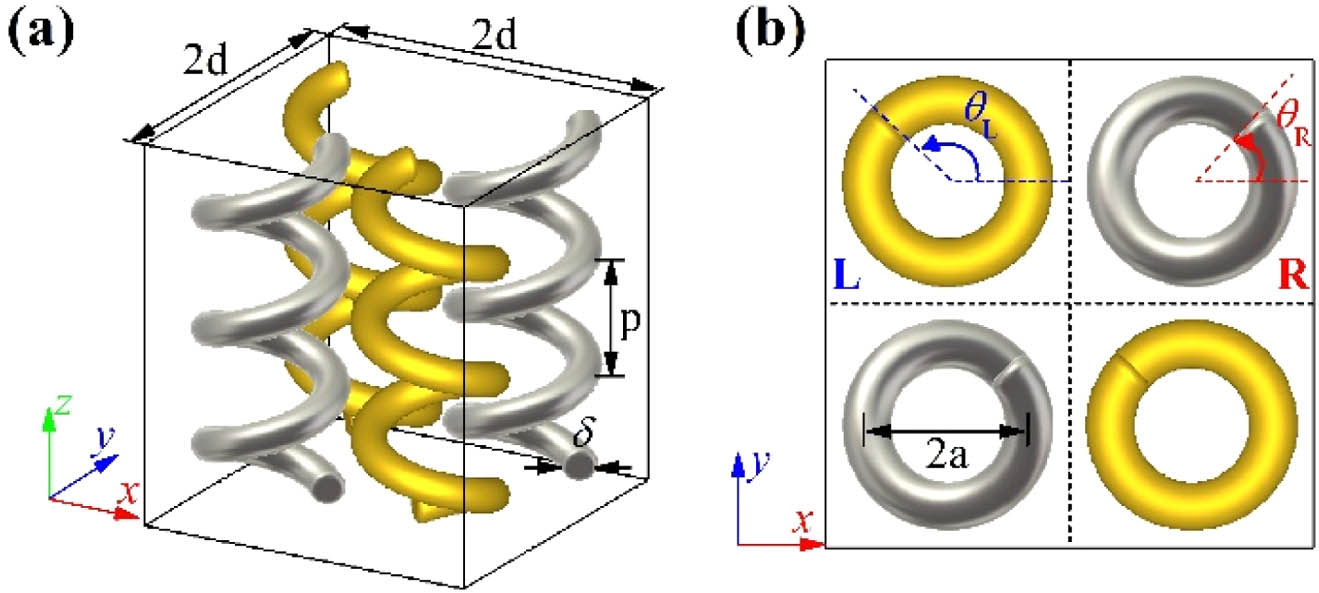
    Figure 1.(a) Schematic of a unit cell of the racemic metallic helix array. (b) Top view of the unit cell.

    (a) Schematic of a unit cell of the 0° oriented RH subarray. (b) Calculated (lines) and measured (circles) reflection spectra of the 0° oriented RH subarray in circular basis. The first and the second subscripts of reflection spectra refer to the polarization states of the reflected and the incident waves, respectively. The reflection spectra are normalized to the power of incidence. (c) Reflection spectra of the RH subarray in its eigen-polarization basis. The calculated (d) tilt angles and (e) ellipticity angles of the RH and LH subarrays with orientation angles of 0°. (f) Reflection phase of states A and A* from the RH and LH subarray, respectively. The circles in (c) and (d) show the corresponding results of the eigen-polarization basis calculated from experimentally measured reflection spectra.

    Figure 2.(a) Schematic of a unit cell of the 0° oriented RH subarray. (b) Calculated (lines) and measured (circles) reflection spectra of the 0° oriented RH subarray in circular basis. The first and the second subscripts of reflection spectra refer to the polarization states of the reflected and the incident waves, respectively. The reflection spectra are normalized to the power of incidence. (c) Reflection spectra of the RH subarray in its eigen-polarization basis. The calculated (d) tilt angles and (e) ellipticity angles of the RH and LH subarrays with orientation angles of 0°. (f) Reflection phase of states A and A* from the RH and LH subarray, respectively. The circles in (c) and (d) show the corresponding results of the eigen-polarization basis calculated from experimentally measured reflection spectra.

    Following the approach in Ref. [42], we find that the eigen-polarization states are a pair of orthogonal elliptical polarization states, denoted as A and B with coordinates (2ψR,2χR) and (2(ψR+90°),2χR) on a Poincaré sphere, respectively. (Details of the methods are presented in Appendix A.) Figure 2(c) shows reflection spectra of 0° oriented RH subarray in its eigenbasis, where no polarization conversion occurs. The tilt angles ψR and ellipticity angles χR of state A are obtained based on calculated and measured reflection spectra and are shown in red color in Figs. 2(d) and 2(e), respectively. The RH subarray shows clearly elliptical dichroism feature, i.e., the RH elliptical state A is mainly reflected with polarization state unchanged, while state B is allowed to pass through without reflection. Especially, the near perfect reflection of state A is obtained around the frequency of 14.4 GHz. As for the LH subarray, since it is mirror-symmetrical to the RH one, a handedness flipped elliptical dichroism feature can be expected, that is, the reflection spectra in the eigenbasis are identical while the eigen-polarization states are mirror symmetrical to those of the RH subarray. These properties have been confirmed by our calculations (reflection spectra of LH subarrays are presented in Appendix A). We denote the eigen-polarization states of the 0° oriented LH subarray as A*(2ψL,2χL) and B*(2(ψL+90°),2χL). As shown in Figs. 2(d) and 2(e), the tilt angles ψL and ellipticity angles χL of state A* (blue) are just in opposite sign to those of state A, which indicates that the two states are mirror-symmetrical to each other about the xoz plane, just like the 0° oriented RH and LH subarrays. In addition, as depicted in Fig. 2(f), the reflection phase of state A* from the LH subarray is also identical to that of state A from the RH subarray, which further demonstrates the mirror-symmetrical relation between the two states. It is necessary to point out that the eigen-polarization states are uniquely related to the principal symmetry of helices. Therefore, when the orientation angle of helices varies, the tilt angles of the eigen-polarization states change by the same value, for example, the Poincaré sphere coordinates corresponding to the eigen-polarization states of the RH subarray with the orientation angle of θ being (2(ψR+θ),2χR) and (2(ψR+θ+90°),2χR). Meanwhile, the ellipticity angles and the reflection spectra in the new eigenbasis are not affected.

    As discussed above, the two subarrays respectively reflect electromagnetic waves of elliptical states of their own handedness. Since the proposed racemic array consists of both RH and LH subarrays, one can intuitively expect electromagnetic waves of both the two elliptical states to interact with matching handedness subarrays and achieve near perfect reflection at 14.4 GHz. To avoid confusion with the eigen-polarization states of subarrays, for the aforementioned racemic array composed of RH and LH helices with orientation angles of θR and θL, these two elliptical states at 14.4 GHz are defined by Poincaré sphere coordinates as ER(2(ψ+θR),2χ) and EL(2(ψθL),2χ), respectively. Then, under the above assumption, the reflection Jones calculus (omitting a global phase delay) of a racemic helix array in a linear polarization basis can be derived as Mθr,θl=R(β)(eiϕx,x00eiϕy,y)R(β),with ϕx,x=2arctan[tan(ψ+α)tanχ],ϕy,y=2arctan[cot(ψ+α)tanχ],where R(β)=(cosβsinβsinβcosβ) denotes the rotation matrix, and α=(θRθL)/2,β=(θR+θL)/2 are half of the difference and summation of the orientation angles of the RH and LH helices, respectively. More discussion about the reflection response of racemic array can be found in Appendix B. As seen from Eq. (1), the reflection feature of the racemic helix array shows great resemblance to a linearly birefringent element. Obviously, the directions of the fast and slow axes as well as the phase retardations along them can be manipulated by tuning the orientation angles of the RH and LH helices. Namely, the directions of the fast and slow axes are determined by the summation of the orientation angles of the RH and LH helices, whereas the phase retardations are determined by the difference between them. Since parameter α may vary from 90° to 90°, it can be obviously seen from Eqs. (2) and (3) that the reflection phases ϕx,x and ϕy,y can be continuously tuned in the range of 0°–360°. It is noteworthy that this phase shift purely originates from geometric transformation and is therefore a geometric phase. In addition, the phase difference between the fast and slow axes can also be manipulated by varying parameter α. Especially, the 180° phase difference can always be acquired when ψ+α equals zero. This provides an approach for polarization conversion.

    The reflection spectra of the racemic helix array are calculated and measured to verify our prediction. The calculation settings and the experimental setup are with the same as those for subarray reflection spectra measurement. All samples for racemic helix array reflection spectra measurement are the same size and consist of 30×30 unit cells. Figure 3(a) shows the result of the racemic array with both RH and LH helices orientation angles being 0°. Clearly, the racemic array is opaque to both the x- and y-polarized electromagnetic waves at 14.4 GHz, and no polarization conversion occurs. We further investigate the amplitude and phase responses of the racemic array with β fixed to be 0° but a varying parameter α. As shown in Figs. 3(b) and 3(c), when parameter α is changed from 90° to 90°, the reflective amplitude constantly retains near unity for both x and y polarizations, whereas both the reflection phases ϕx,x and ϕy,y have a 360° range variation. To show phase response to parameter α more clearly, the reflection phases ϕx,x and ϕy,y are shown in Fig. 3(d) as phase shifts, and the reflection phase of x polarization for the racemic array with both parameters α and β being 0° is set to be the reference value. Clearly, the reflection phase from 0° to 360° can be achieved for both polarizations by tuning parameter α. Following Eqs. (2) and (3), we find that, for the two nearly perfectly reflected elliptical states at 14.4 GHz, the tilt and ellipticity angles are ψ0° and χ22.5°, respectively. It can be noticed that these two elliptical states are slightly different from the states A and A* of the RH and LH subarrays at 14.4 GHz. This is due to the mutual coupling between helices of different handedness, though rather weak (more discussions can be found in Appendix B). The reflection phases ϕx,x and ϕy,y obtained from Eqs. (2) and (3) with ψ=0° and χ=22.5° are shown in Fig. 3(d) with solid lines, which are in excellent agreement with calculated and measured ones. It is necessary to point out that such phase modulation is achieved purely by exploiting the PB geometric phase. Consider the case in which β is fixed to be 0°; the two near perfectly reflected elliptical states at 14.4 GHz are ER(2α,2χ) and EL(2α,2χ). Since the incident wave is along the opposite direction, these two states are ER*(2α,2χ) and EL*(2α,2χ) in the incident coordinate system. For example, the incident x-polarized wave can be regarded as the superposition of electromagnetic waves of ER* and EL* states with the same amplitude and phase. As shown in Fig. 3(e), the two parts of incident wave respectively experience the polarization evolution paths of xER*ERx and xEL*ELx, and they accumulate the same geometric phase, which can be quantified by Eq. (2). Then, the reflected x-polarized wave exhibits a phase shift with the parameter α. It is worth noting that, due to the difference in polarization evolution path, the phase difference between the reflective x- and y-polarized components is also varying as parameter α changes. As shown in Fig. 3(f), the phase difference Δϕ=ϕy,yϕx,x can roughly cover the ranges of [180°,90°] and [90°, 180°], which indicates that the proposed racemic array possesses various reflective polarization conversion abilities including but not limited to the functions of the half-wave plate and quarter-wave plate. In addition, combined with parameter β, which decides the directions of the fast and slow axes, the versatile modulations of polarization, phase, and amplitude of the electromagnetic waves can be achieved, and a variety of wavefront manipulations can also be obtained. In the following sections, we shall discuss these features in detail.

    (a) Reflection spectra of a racemic array with both RH and LH helices’ orientation angles being 0°; (b) reflectance and (c) reflection phase responses as functions of parameter α at 14.4 GHz (the parameter β is fixed to be 0°); (d) reflection phase shift of x and y polarizations as functions of parameter α, compared to the reflection phase of x polarization for a racemic array with both parameters α and β being 0°; (e) polarization evolution paths of x polarization on the Poincaré sphere; (f) the reflection phase difference Δϕ=ϕy,y−ϕx,x as functions of parameter α. The theoretical results in (d) and (f) are obtained from Eqs. (2) and (3) with ψ=0° and χ=22.5°. Circles in Fig. 3 show the corresponding measured results.

    Figure 3.(a) Reflection spectra of a racemic array with both RH and LH helices’ orientation angles being 0°; (b) reflectance and (c) reflection phase responses as functions of parameter α at 14.4 GHz (the parameter β is fixed to be 0°); (d) reflection phase shift of x and y polarizations as functions of parameter α, compared to the reflection phase of x polarization for a racemic array with both parameters α and β being 0°; (e) polarization evolution paths of x polarization on the Poincaré sphere; (f) the reflection phase difference Δϕ=ϕy,yϕx,x as functions of parameter α. The theoretical results in (d) and (f) are obtained from Eqs. (2) and (3) with ψ=0° and χ=22.5°. Circles in Fig. 3 show the corresponding measured results.

    3. PHASE MODULATION FOR LINEAR POLARIZATION

    As discussed in the previous section, the reflection features of a racemic helix array are essentially similar to linearly birefringent elements. Especially, arbitrary phase retardations along the fast and slow axes can be obtained by exploiting the geometric phase introduced by the orientation angles of the RH and LH helices. Unlike the traditional PB phase elements, which are limited to circularly polarized waves, the phase modulation mechanism we find in a racemic helix array is capable of full phase range coverage for linearly polarized waves. To demonstrate the validity of our phase modulation approach, we design and characterize a reflective vortex beam generator built with a racemic helix array. Vortex beams with orbital angular momentum have attracted great interest due to the fascinating properties and numerous applications, such as high-resolution imaging [43,44], particle manipulation [45,46], and optical communications [4749]. Such beam has a helical phase front of exp(ilφ), where φ is the azimuthal angle and l is the topological charge of the beam. The desired helical phase front can be realized by arranging optical elements with azimuthally evolving transmission or reflection phase.

    As shown in Fig. 3, by tuning the parameter α, the full range control of reflection phase can be obtained for both x- and y-polarized waves. Intuitively, the helical phase front of the vortex beam can be obtained by azimuthally varying parameters α of unit cells in a racemic helix array. For example, to generate an x-polarized vortex beam with topological charge l, the parameters β for all unit cells are fixed to be 0°, i.e., the orientation angles of the RH and LH helices are in opposite signs in each unit cell. Meanwhile, the parameters α of unit cells are determined by Eq. (2) to ensure the reflection phase of unit cells equals to l·φu (φu is azimuthal angle of the unit cell). Then, a normally incident x-polarized beam will be reflected with polarization state unchanged, and the wavefront is converted to helical wavefront that carries an orbital angular momentum of l per photon.

    Figures 4(a) and 4(b) show the photo of the device for generating an x-polarized vortex beam with topological charge l=1 and the enlarged view of a unit cell. For simplifying the calculation and experiment, the device is designed with only eight racemic helix unit cells with aforementioned parameters, which form a 3×3 square array (the center is left to be empty) and are counterclockwise labeled as unit cells 0–7. Following the scheme states above, the orientation angles of RH helices in 0–7 unit cells are set to be 0°, 45°, 67.2°, 80.2°, 90°, 80.2°, 67.2°, and 45°, respectively. The orientation angles of LH helices in each unit cell is in opposite sign to the RH ones to ensure that the reflection phases of the unit cells have a phase shift that varies azimuthally from 0° to 360° with a step of 45°. The performances of vortex beam generator are also measured in an anechoic chamber with a Keysight PNA-X 5242A network analyzer. A linearly polarized horn antenna is used as emitter to generate an x-polarized wave that is normally incident to the sample. To characterize the generated vortex beam, the reflected fields are detected with a small dipole antenna as probe and the measuring plane is 100 mm away from the sample surface. The electric field amplitude and phase of reflected x-polarized components are measured as a function of transverse position in a precision of 1 mm per step. More details about the experimental setup can be found in the Appendix C. The calculated and measured results at 14.4 GHz, which are in good agreement, are shown in Figs. 4(c)–4(f). In the simulations, perfectly matched layers with a vacuum spacer are applied at all boundaries. An x-polarized plane wave along the z direction is used to excite the sample, and the scattered x-polarized electric field is recorded. The helical phase feature and the characteristic doughnut shape amplitude distributions can be clearly recognized. In addition, as indicated by Eq. (1), the directions of fast and slow axes can be changed by altering the parameter β. Then, full range of phase control can be achieved for arbitrary linear polarization by tuning the parameter α. Furthermore, the racemic helix array can also be used for phase modulation of circular polarizations. As discussed above, 180° phase difference between the fast and slow axes can always be acquired, which implies that the racemic array behaves like a reflective half-wave plate that reflects circularly polarized waves without polarization state change. Obviously, additional geometric phase can be introduced to the reflected circularly polarized waves by altering the parameter β.

    (a) Photograph of the device for generating vortex beam with topological charge l=1; (b) enlarged view of a unit cell; (c), (d) calculated and (e), (f) measured electric field amplitude and phase distribution of the vortex beam with topological charge l=1 at 14.4 GHz on the transverse plane 100 mm away from the device surface. The electric field distributions are normalized to the global maximum.

    Figure 4.(a) Photograph of the device for generating vortex beam with topological charge l=1; (b) enlarged view of a unit cell; (c), (d) calculated and (e), (f) measured electric field amplitude and phase distribution of the vortex beam with topological charge l=1 at 14.4 GHz on the transverse plane 100 mm away from the device surface. The electric field distributions are normalized to the global maximum.

    4. POLARIZATION CONVERSION

    An important feature we found in the racemic helix array is the ability of polarization conversion. As mentioned in previous sections, the racemic helix array behaves like a linearly birefringent element with tunable orientation and phase retardation along the fast and slow axes. Moreover, the phase difference between field components polarized along the fast and slow axes can also be modulated by rotation of the helices, which provides a variety of polarization conversion possibilities.

    We first investigate the feature of racemic helix array rotating the polarization direction of a linearly polarized wave. As can be seen in Fig. 3, when both the parameters α and β are 0°, the proposed racemic helix array behaves like a reflective half-wave plate with fast and slow axes along the x and y directions, respectively. In addition, as implied by Eq. (1), the fast and slow axes can be rotated by tuning the parameter β. Then, a linearly polarized incident waves can be reflected with polarization rotation of arbitrary angle. As verification, reflection measurements are performed inside an anechoic chamber with two racemic helix array samples of the aforementioned geometric parameters. Both samples consist of 30×30 unit cells (all polarization conversion samples are in the same size), and the parameter α is set to be 0° for both samples, while the parameter β is 45° and 22.5°, respectively. For comparison, numerical simulations are also conducted to calculate the reflection spectra. In these calculations, the settings are the same as those used in Section 2. As shown in Figs. 5(a) and 5(b), x- and y-polarized incident waves are near perfectly reflected with a 90° polarization rotation by the racemic helix array of β=45° at 14.4 GHz, and the measured results are in good agreement with the calculated ones. As for the sample of β=22.5°, it can be seen from the results in Figs. 5(c) and 5(d) that the polarization angles of the x- and y-polarized incident waves are perfectly transformed to 45° and 45°, respectively.

    Reflection spectra of racemic helix array samples as a reflective half-wave plate. Reflection spectra are calculated and measured for two samples with parameter β of (a), (b) 45° and (c), (d) 22.5°. The parameter α for both samples is 0°. The symbol 45 or −45 denotes linear polarization with a polarization angle of 45° or −45° about the x axis. The reflection spectra are normalized to the power of incidence.

    Figure 5.Reflection spectra of racemic helix array samples as a reflective half-wave plate. Reflection spectra are calculated and measured for two samples with parameter β of (a), (b) 45° and (c), (d) 22.5°. The parameter α for both samples is 0°. The symbol 45 or 45 denotes linear polarization with a polarization angle of 45° or 45° about the x axis. The reflection spectra are normalized to the power of incidence.

    It is noteworthy that, as indicated by Eqs. (2) and (3), 180° phase difference between field components polarized along the fast and slow axes can always be achieved. Then the feature of rotating the polarization direction of a linearly polarized wave can be implemented with a racemic helix array of arbitrary geometric parameters. However, suitable chosen parameters can expand the range of phase difference and provide various polarization conversion features. For example, as shown in Fig. 3, the proposed racemic helix array can introduce phase difference in the ranges of [180°,90°] and [90°, 180°]. Conspicuously, linear-to-circular polarization conversion (or vice versa) of a quarter-wave plate can also be realized with the proposed racemic helix array. Based on the analysis stated above, we investigate a racemic helix array sample of which both parameters α and β are 45°. As shown in Figs. 6(a) and 6(b), just as expected, both the calculations and measurements demonstrate that the reflected waves are transformed to be LCP or RCP, respectively, under x- or y-polarized incidence at 14.4 GHz. In fact, since the phase difference and the directions of the fast and slow axes are tunable with the parameters α and β, diverse polarization conversion can be obtained with the racemic helix array. Consider the RCP incidence case; the reflected wave can be expressed with its Jones vector as E=Mθr,θl·(1i)=ei(ϕxβ)R(β)(1ei(Δϕπ/2)).

    (a), (b) Reflection spectra of racemic helix array sample as a reflective quarter-wave plate. The parameters α, β of the sample are both 45°. (c), (d) Theoretical and (e), (f) calculated tilt angles ψ′ and ellipticity angles χ′ of the reflected waves under RCP incidence as functions of parameters α and β. The theoretical results are obtained from Eqs. (2)–(4) with ψ=0° and χ=22.5°. (g), (h) Reflection spectra of the racemic helix array sample that converts circular polarization states to elliptical polarization states. The parameters α, β of the sample are 12° and 15°, respectively. The tilt angle and ellipticity angle of polarization state γ are 60° and 22.865°, respectively. State γ′ is orthogonal to γ, and its tilt angle and ellipticity angle are 150° and −22.865°.

    Figure 6.(a), (b) Reflection spectra of racemic helix array sample as a reflective quarter-wave plate. The parameters α, β of the sample are both 45°. (c), (d) Theoretical and (e), (f) calculated tilt angles ψ and ellipticity angles χ of the reflected waves under RCP incidence as functions of parameters α and β. The theoretical results are obtained from Eqs. (2)–(4) with ψ=0° and χ=22.5°. (g), (h) Reflection spectra of the racemic helix array sample that converts circular polarization states to elliptical polarization states. The parameters α, β of the sample are 12° and 15°, respectively. The tilt angle and ellipticity angle of polarization state γ are 60° and 22.865°, respectively. State γ is orthogonal to γ, and its tilt angle and ellipticity angle are 150° and 22.865°.

    Note that the Jones vector for incident RCP wave is [1,i]T in the incident coordinate system. The last term represents a polarization state with tilt angle of either 45° or 135°, and the ellipticity angle is determined by the phase difference Δϕ, or in other words, determined by parameter α and the two near perfectly reflected elliptical states ER and EL according to Eqs. (2) and (3). In addition, since the second term in Eq. (4) represents a rotation operation, it is clear that the tilt angle of reflected polarization waves is linearly dependent on the parameter β. The theoretical and calculated tilt angles ψ and ellipticity angles χ of the reflected waves of the proposed racemic helix array under RCP incidence are shown in Figs. 6(c)–6(f). The results are presented at 14.4 GHz as functions of parameters α and β. As expected, the arbitrary tilt angle can be obtained by tuning parameter β, whereas the ellipticity angle can be modulated in the range of [0°, 45°] by tuning parameter α. This indicates that by tuning the parameters α and β, RCP waves can be converted to any right-handed elliptical polarization or any linear polarization states, that is, all the polarization states on the equator and northern hemisphere of the Poincaré sphere. Similar discussions are also applicable to the LCP incidence case, and it can be found that the reflected wave can be converted to any polarization state on the equator and southern hemisphere of the Poincaré sphere. In addition, the polarization state of the reflected wave under LCP incidence is always orthogonal to the one under RCP incidence.

    Without loss of generality, a racemic helix array of which the parameters α and β are 12° and 15° is chosen to demonstrate the polarization conversion from a circular to an elliptical state. Based on the above theory, an RCP incident wave will be converted to an elliptical state γ, of which the tilt angle and ellipticity angle are 60° and 22.865°, respectively. An LCP incident wave will be converted to the orthogonal state γ with tilt angle and ellipticity angle of 150° and 22.865°. The calculated and measured results are shown in Figs. 6(g) and 6(h). Clearly, the incident RCP and LCP waves are perfectly converted to γ and γ states at 14.4 GHz, respectively. It is necessary to point out that the polarization conversion capabilities for circular incidence are directly related to the phase difference Δϕ between field components polarized along the fast and slow axes. Take the RCP incidence case for example: the possible polarization states of the reflected wave can be expanded to cover all states above a specific latitude line of the southern hemisphere of the Poincaré sphere. This can be realized with racemic array of smaller pitch size, of which the ellipticity angles χ of the two near perfectly reflected elliptical states are smaller. Although we only demonstrate some typical polarization conversion features of the racemic helix array, it is possible to achieve more diverse polarization conversion functionalities by optimizing geometric parameters or designing a racemic unit cell that breaks the mirror symmetry.

    5. COMPLEX AMPLITUDE MODULATION

    Another interesting feature of the racemic helix array is the ability of modulation over the amplitude of reflected waves. As discussed above, a 180° phase difference between electric field components polarized along the fast and slow axes can be obtained for a racemic helix array of arbitrary geometric parameters, that is, the racemic helix array behaves like a reflective half-wave plate. Then, its reflection Jones calculus (omitting a global phase delay) can be derived from Eq. (1) as M=R(β)(1001)R(β)=(cos2βsin2βsin2βcos2β).

    Clearly, for x- or y-polarized incident waves, the cross-polarized reflection coefficient is sin2β, which implies a continuous amplitude modulation from zero to unity along with binary phase 0° or 180°. As mentioned above, the proposed racemic helix array of parameter α=0° meets the criteria of a reflective half-wave plate. Figure 7(a) shows the calculated reflection amplitude spectra of xtoy conversion components of a racemic helix array with parameter β of 0°, 15°, 30°, and 45°, while the parameter α is fixed to be 0°. It is obvious that the reflection amplitude of the x-to-y conversion component varies from zero to unity at 14.4 GHz as the parameter β changes. To show the relationship between the reflection coefficient and parameter β more clearly, the reflection amplitude and phase of the x-to-y conversion component versus parameter β at 14.4 GHz are shown in Fig. 7(b). Clearly, good agreements can be observed between the calculated results and the theoretical predictions.

    (a) Calculated reflection amplitude of the x-to-y polarization conversion component for a racemic helix array with β=0°, 15°, 30°, and 45°. The parameter α is fixed to be 0°. (b) Reflection amplitude (blue squares) and phase (black circles) of the x-to-y polarization conversion component as a function of parameter β at 14.4 GHz. Theoretical and calculated (c), (e) amplitude and (d), (f) phase of the reflected co-polarized components under x-polarized incidence as a function of parameters α and β at 14.4 GHz. The theoretical results are obtained from Eqs. (1) and (2) with ψ=0° and χ=22.5°.

    Figure 7.(a) Calculated reflection amplitude of the x-to-y polarization conversion component for a racemic helix array with β=0°, 15°, 30°, and 45°. The parameter α is fixed to be 0°. (b) Reflection amplitude (blue squares) and phase (black circles) of the x-to-y polarization conversion component as a function of parameter β at 14.4 GHz. Theoretical and calculated (c), (e) amplitude and (d), (f) phase of the reflected co-polarized components under x-polarized incidence as a function of parameters α and β at 14.4 GHz. The theoretical results are obtained from Eqs. (1) and (2) with ψ=0° and χ=22.5°.

    In fact, similar continuous amplitude modulation with binary phase response has been discovered with anisotropic elements and utilized for exotic application like Airy beam generation [5052]. Obviously, a racemic helix array is also capable of implementing similar wavefront manipulations. However, since the reflection feature of the proposed racemic helix array is also determined by the parameter α, through this extra degree of freedom, more flexible complex amplitude modulations can be achieved. Consider the co-polarized reflection component of racemic helix array under x-polarized incidence; its reflection coefficient can be derived from Eq. (1) as rx,x=cos2βeiϕx,x+sin2βeiϕy,y.

    Obviously, the complex amplitude modulation feature is closely related to the phase difference Δϕ=ϕy,yϕx,x, which is mainly determined by the ellipticity angle χ of the two near perfectly reflected elliptical states ER* and EL*. Although the amplitude and phase of reflection coefficient rx,x usually cannot be expressed with a simple function of parameters α and β, a full range of complex amplitude modulation can always be implemented with a racemic helix array. The amplitude and phase of reflection coefficient rx,x at 14.4 GHz are obtained by both theoretical analysis and numerical calculation for the proposed racemic helix array, which are shown in Figs. 7(c)–7(f). Clearly, the calculated results show good agreement with the theoretical ones. In addition, through more careful analysis, we find that a free combination of reflection amplitude from 0 to 1 and reflection phase of 180° to 180° can be achieved by tuning the parameters α and β.

    To further demonstrate the full range complex amplitude modulation feature, we design and characterize a bifocal metalens with two laterally aligned foci, which demands continuous full range control of amplitude and phase. The required complex amplitude distributions on a bifocal metalens aperture can be expressed as A(x,y,λ0)=A1ei2πλ0((xx1)2+(yy1)2+f12f1)+A2ei2πλ0((xx2)2+(yy2)2+f22f2),where A1 and A2 are the amplitudes of two foci with focal lengths f1 and f2, respectively, (x1,y1) and (x2,y2) are lateral positions of two foci with respect to the lens center, and λ0 represents the free space wavelength of operating frequency. For simplifying the calculation and experiment, a cylindrical metalens in the x direction is designed for demonstration, and the required complex amplitude distributions are reduced to A(x,λ0)=A1ei2πλ0((xx1)2+f12f1)+A2ei2πλ0((xx2)2+f22f2).

    The lateral bifocal metalens is designed at 14.4 GHz, and contains a total of 961 aforementioned racemic helix unit cells, which form a 31×31 square array. The two foci are set with the same amplitude and the same focal length f1=f2=540  mm, with 150 mm lateral distance (x1=75  mm and x2=75  mm). The designed amplitude and phase distributions along the x direction are shown in Figs. 8(a) and 8(b). The red solid lines show the continuous distribution calculated by Eq. (8), whereas the blue squares correspond to the discretized ones by sampling Eq. (8) with a period of 20 mm. The orientation angles of helices in each unit cell are determined by searching for values of Eq. (6) in the space of parameters α and β to achieve the desired amplitude and phase that are decided by its position on the x direction. Once the required parameters α and β are found, the orientation angles θR and θL can be obtained. For example, the unit cell at x=0  mm is required to generate an amplitude of 1 and a phase of 88.6°, and by searching parameters α and β based on Eq. (6), it can be found that the parameters α and β are 67° and 0°, and then the orientation angles θR and θL can be determined as 67° and 67°. The unit cells along the y direction are identical. The experimental setup is the same as those we employed to characterize the generated vortex beam in Section 3, except that the measurements are performed on the xoz plane.

    Required (red solid lines) and sampled (blue squares) normalized (a) amplitude and (b) phase distributions of the designed lateral bifocal cylindrical metalens. (c) Calculated and (d) measured x-polarized electric field amplitude distributions on the xoz plane at 14.4 GHz. (e) Calculated and measured x-polarized electric field amplitude along the white dashed line (y=0 mm, z=540 mm) shown in (c) and (d). All amplitude distributions are normalized to their global maximum.

    Figure 8.Required (red solid lines) and sampled (blue squares) normalized (a) amplitude and (b) phase distributions of the designed lateral bifocal cylindrical metalens. (c) Calculated and (d) measured x-polarized electric field amplitude distributions on the xoz plane at 14.4 GHz. (e) Calculated and measured x-polarized electric field amplitude along the white dashed line (y=0  mm, z=540  mm) shown in (c) and (d). All amplitude distributions are normalized to their global maximum.

    The calculated and measured results of lateral bifocal lens at 14.4 GHz are shown in Figs. 8(c)–8(e). In these calculations, periodic boundary conditions are applied at the y boundaries, perfectly matched layers with vacuum spacer are applied at the x boundaries, and perfectly matched layers are applied at the z boundaries. The other settings are the same as those used in Section 3. The two maxima at the preset focal plane (i.e., f1=f2=540  mm) can be clearly observed in both results. The amplitude distribution across the two foci on the focal plane (along the line of y=0  mm) is shown in Fig. 8(e), from which the lateral distance between two foci is calculated. As expected, the measurement and calculation agree well with each other and confirm the design goals. Note that the continuous amplitude and phase pattern required for a 2D bifocal metalens are also achievable with the proposed racemic helix array. In addition, similar to the polarization conversion feature, it is possible to realize more diverse complex amplitude modulation with a racemic array by further design development.

    6. CONCLUSION

    In summary, we have shown that, based on the PB phase associated with the two elliptical eigen-polarization states, novel properties including full range phase modulation for linearly polarized states, diverse polarization conversion, and full complex amplitude modulation can be achieved by tuning the helices’ orientation of the racemic array. As verification, several racemic helix array samples that are capable of generating vortex beams, polarization conversion, and lateral dual focusing are fabricated and characterized in the microwave regime. The proposed modulation strategy on phase, polarization and amplitude may stimulate various novel and high-performance metadevices. In addition, utilizing advanced fabrication technology [31,53] and discrete chiral systems like twisted cascaded structures [28] and chiral nematic liquid crystals [3234], our findings can be generalized to other frequency regimes such as THz, infrared, and even visible light.

    APPENDIX A: REFLECTIVE EIGEN-POLARIZATION STATES OF SUBARRAYS

    Similarly to the approach in Ref. [42] for transmission case, to determine the reflective eigen-polarization states is to solve the following eigenvalue problem: Msub(1001)(exey)=κ(exey),where Msub=(rx,xrx,yry,xry,y) is the reflection Jones calculus in linear polarization basis, matrix (1001) represents the transformation from an incident to a reflective coordinate system, and [ex,ey]T and κ are the eigenvector and eigenvalue, respectively. By solving Eq. (A1), we obtain κ1,2=rx,xry,y±(rx,x+ry,y)24rx,yry,x2.

    Then, ex and ey can be solved by simply inserting κ1,2 into Eq. (A1), and the reflective eigen-polarization states can be derived as e1=(1R1eiη1),e2=(1R2eiη2),with R1eiη1=rx,xκ1rx,y, and R2eiη2=rx,xκ2rx,y. Though the eigenvectors are not normalized, the tilt and ellipticity angles of the reflective eigen-polarization states can be derived from them as ψ1=12arctan(2R1cosη11R12),χ1=12arcsin(2R1sinη11+R12),ψ2=12arctan(2R2cosη21R22),χ2=12arcsin(2R2sinη21+R22).

    The eigenvalues κ1,2 are just the co-polarization reflection coefficients for these two eigen-polarization states. Meanwhile, there are no polarization conversions between these two states. Note that this method of determining the reflective eigen-polarization states is universal for all periodic metamaterials. The results of subarrays shown in Figs. 2(c)–2(f) are obtained by the above method. Since the helix possess C2 symmetry, as discussed in Ref. [42], the eigenvectors e1 and e2 are orthogonal.

    For the sake of completeness, additional calculation results of subarrays are shown in Fig. 9. As mentioned above, the subarrays will allow circularly polarized waves of opposite handedness to pass through along the axial direction, while the matching handedness waves are coupled with helices and reflected with the same handedness. Figure 9(a) shows the calculated transmission spectra in circular basis of an RH subarray with 0° orientation angle. Clearly, the LCP waves are mainly transmitted in a wide frequency range as expected. Calculated reflection and transmission spectra in the circular basis of LH subarray with 0° orientation angle are shown in Figs. 9(b) and 9(c). Compared to the corresponding results of the RH subarray shown in Figs. 2(b) and 9(a), it can be found that the reflection and transmission features of the LH subarray are identical but in the opposite handedness. This is due to the mirror symmetry between them. Figure 9(d) shows the reflection spectra of the 0° oriented LH subarray in its eigen-polarization basis. As expected, the results are also identical to those for the 0° oriented RH subarray shown in Fig. 2(c).

    (a) Calculated transmission spectra of the 0° oriented RH subarray in circular basis. (b) Calculated reflection spectra of the 0° oriented LH subarray in circular basis. (c) Calculated transmission spectra of the 0° oriented LH subarray in circular basis. (d) Reflection spectra of the 0° oriented LH subarray in its eigen-polarization basis.

    Figure 9.(a) Calculated transmission spectra of the 0° oriented RH subarray in circular basis. (b) Calculated reflection spectra of the 0° oriented LH subarray in circular basis. (c) Calculated transmission spectra of the 0° oriented LH subarray in circular basis. (d) Reflection spectra of the 0° oriented LH subarray in its eigen-polarization basis.

    APPENDIX B: REFLECTION RESPONSE OF THE RACEMIC ARRAY

    For the subarrays, the reflection of the matching handedness elliptical state is a collective effect between local resonance of a single helix and the scattering of the array, whereas the opposite handedness state is not interacting with helices and passes through. As for the racemic helix array, it combines two subarrays in opposite handedness with a spatial deviation. Therefore, when an electromagnetic wave is incident to the racemic helix array, components of the two elliptical eigenstates will respectively interact with matching handedness subarrays and be perfectly reflected with polarization state unchanged.

    Under this assumption, we derived the reflection Jones calculus of the racemic helix array in a linear polarization basis by considering the reflection under x- and y-polarized incidence. Considering a racemic array composed of RH and LH helices with orientation angles of θR and θL, the two perfectly reflected elliptical states are ER(2(ψ+θR),2χ) and EL(2(ψθL),2χ), respectively. Then, for an x-polarized incident wave, it can be regarded as superposition of field components of ER and EL states in the incident coordinate system and expressed as (10)=AR·R(ψθr)(1001)(cosχisinχ)+AL·R(ψθl)(1001)(cosχisinχ),where AR and AL are the amplitude of components of the ER and EL states. As discussed in Section 2, the reflection phases of components of the ER and EL states are the same. Then, the reflective field can be expressed with its Jones vector as rx=AR·R(ψθr)(cosχisinχ)+AL·R(ψθl)(cosχisinχ).

    After some derivation, it can be obtained that rx=(cos2βeiϕx,x+sin2βeiϕy,ysinβcosβeiϕx,xsinβcosβeiϕy,y),where ϕx,x and ϕy,y can be derived in this procedure as eiϕx,x=cos(ψ+α)cosχisin(ψ+α)sinχcos(ψ+α)cosχ+isin(ψ+α)sinχ,eiϕy,y=sin(ψ+α)cosχ+icos(ψ+α)sinχsin(ψ+α)cosχicos(ψ+α)sinχ,and then be simplified to the expressions shown in Eqs. (2) and (3). Similar analysis can also be applied for the y-polarized incident wave, and the reflective field can be expressed as ry=(sinβcosβeiϕx,xsinβcosbeiϕy,ysin2βeiϕx,x+cos2βeiϕy,y).

    Obviously, the Jones vectors rx and ry contain the four reflection coefficients of the racemic helix array, and hence we can derive the expression shown in Eq. (1). In addition, as discussed in Section 2, phase ϕx,x is the geometric phase that accumulated along the polarization evolution path xER*ERx. Correspondingly, ϕy,y is the PB geometric phase introduced with the yER*ERy polarization evolution. These two phases can also be calculated by the definition of PB phase, which is calculating half of the solid angle of the area enclosed by the polarization evolution loop. With the tilt and ellipticity angles of all corresponding states, this can be implemented by calculating a spherical excess.

    To determine the two near perfectly reflected elliptical states of racemic helix array, we first calculate reflection features of racemic arrays with β fixed to be 0° and the parameter α being changed from 90° to 90°. The tilt and ellipticity angles are then obtained by data fitting according to Eqs. (2) and (3), and they are found to be ψ0° and χ22.5°. This result is further verified by comparing numerical calculations of the racemic array with arbitrary α and β parameters and theoretical predictions obtained from Eqs. (2) and (3) with ψ0° and χ22.5°.

    As mentioned in Section 2, the two near perfectly reflected elliptical states of the racemic helix array are slightly different from the states A and A* of the RH and LH subarrays at 14.4 GHz. This is mainly attributed to the weak coupling between subarrays decided by the symmetry of the helix. The helix possesses the continuous helical symmetry and periodicity along the helical axis (z axis), and the field components for the RH subarray can be expanded in the cylindrical coordinate system by functions of the form fn(ρ,φ,z)=eikzzFn(ρ)einφei(2nπ/p)z [41], where kz is the Bloch vector along the z axis, and Fn(ρ) is a radial function that obeys the Helmholtz differential equation. The angular term will be einφ for the LH subarray. Since fn(ρ,φ,z) is a serial of basis functions that are orthogonal to each other and the difference in angular term leads to orthogonality between basis functions for RH and LH subarrays, it can be found that only the terms with n=0 for RH and LH subarrays will interact with each other. Therefore, there will be rather weak coupling between subarrays of different handedness, which results in a slight difference between the two near perfectly reflected elliptical states of the racemic helix array and those of the subarrays. In addition, since the angular terms vanish when n=0, the coupling between subarrays is irrelevant to the helices’ orientations, and the two near perfectly reflected elliptical states can be independently modulated by subarrays with matching handedness.

    APPENDIX C: EXPERIMENTAL SETUP

    Figure 10(a) shows the photograph of the experimental setup for characterizing the vortex beam generation and the lateral bifocal lens. The horn antenna is also placed about 3 m away from the sample to mimic an incident plane wave. The reflected field is detected with a small dipole antenna as probe. The measurements are performed with a three-dimensional motorized translation stage to move the probe pixel by pixel on the predesigned scanning plane. The photograph of the experimental setup for reflection spectra and polarization conversion measurement is shown in Fig. 10(b). Two linearly polarized horn antennas are placed close to each other and about 3 m away from the samples.

    Photograph of the experimental setup. (a) Experimental setup for characterizing the vortex beam generation and the lateral bifocal lens; (b) experimental setup for reflection spectra and polarization conversion measurement.

    Figure 10.Photograph of the experimental setup. (a) Experimental setup for characterizing the vortex beam generation and the lateral bifocal lens; (b) experimental setup for reflection spectra and polarization conversion measurement.

    References

    [1] M. V. Berry. Quantal phase factors accompanying adiabatic changes. Proc. R. Soc. London A, 392, 45-57(1984).

    [2] J. Anandan. The geometric phase. Nature, 360, 307-313(1992).

    [3] E. Cohen, H. Larocque, F. Bouchard, F. Nejadsattari, Y. Gefen, E. Karimi. Geometric phase from Aharonov–Bohm to Pancharatnam–Berry and beyond. Nat. Rev. Phys., 1, 437-449(2019).

    [4] Y. Aharonov, D. Bohm. Significance of electromagnetic potentials in the quantum theory. Phys. Rev., 115, 485-491(1959).

    [5] M. R. Pahlavani, F. D. Zela. The Pancharatnam-Berry phase: theoretical and experimental aspects. Theoretical Concepts of Quantum Mechanics(2012).

    [6] S. Pancharatnam. Generalized theory of interference and its applications. Proc. Indian Acad. Sci. A, 44, 247-262(1956).

    [7] G. Li, S. Chen, N. Pholchai, B. Reineke, P. W. H. Wong, E. Y. B. Pun, K. W. Cheah, T. Zentgraf, S. Zhang. Continuous control of the nonlinearity phase for harmonic generations. Nat. Mater., 14, 607-612(2015).

    [8] X. Xie, M. Pu, J. Jin, M. Xu, Y. Guo, X. Li, P. Gao, X. Ma, X. Luo. Generalized Pancharatnam-Berry phase in rotationally symmetric meta-atoms. Phys. Rev. Lett., 126, 183902(2021).

    [9] X. Chen, L. Huang, H. Muhlenbernd, G. Li, B. Bai, Q. Tan, G. Jin, C. W. Qiu, S. Zhang, T. Zentgraf. Dual-polarity plasmonic metalens for visible light. Nat. Commun., 3, 1198(2012).

    [10] M. Khorasaninejad, W. T. Chen, R. C. Devlin, J. Oh, A. Y. Zhu, F. Capasso. Metalenses at visible wavelengths: diffraction-limited focusing and subwavelength resolution imaging. Science, 352, 1190-1194(2016).

    [11] L. Huang, X. Chen, H. Mühlenbernd, G. Li, B. Bai, Q. Tan, G. Jin, T. Zentgraf, S. Zhang. Dispersionless phase discontinuities for controlling light propagation. Nano Lett., 12, 5750-5755(2012).

    [12] M. Q. Mehmood, S. Mei, S. Hussain, K. Huang, S. Y. Siew, L. Zhang, T. Zhang, X. Ling, H. Liu, J. Teng, A. Danner, S. Zhang, C. W. Qiu. Visible-frequency metasurface for structuring and spatially multiplexing optical vortices. Adv. Mater., 28, 2533-2539(2016).

    [13] A. N. Gabriel Biener, V. Kleiner, E. Hasman. Formation of helical beams by use of Pancharatnam–Berry phase optical elements. Opt. Express, 27, 1875-1877(2002).

    [14] R. C. Devlin, A. Ambrosio, D. Wintz, S. L. Oscurato, A. Y. Zhu, M. Khorasaninejad, J. Oh, P. Maddalena, F. Capasso. Spin-to-orbital angular momentum conversion in dielectric metasurfaces. Opt. Express, 25, 377-393(2017).

    [15] E. Karimi, S. A. Schulz, I. De Leon, H. Qassim, J. Upham, R. W. Boyd. Generating optical orbital angular momentum at visible wavelengths using a plasmonic metasurface. Light Sci. Appl., 3, e167(2014).

    [16] Y. Guo, S. Zhang, M. Pu, Q. He, J. Jin, M. Xu, Y. Zhang, P. Gao, X. Luo. Spin-decoupled metasurface for simultaneous detection of spin and orbital angular momenta via momentum transformation. Light Sci. Appl., 10, 63(2021).

    [17] G. Ruffato, P. Capaldo, M. Massari, E. Mafakheri, F. Romanato. Total angular momentum sorting in the telecom infrared with silicon Pancharatnam-Berry transformation optics. Opt. Express, 27, 15750-15764(2019).

    [18] B. Wang, Y. Wen, J. Zhu, Y. Chen, S. Yu. Sorting full angular momentum states with Pancharatnam-Berry metasurfaces based on spiral transformation. Opt. Express, 28, 16342-16351(2020).

    [19] G. Zheng, H. Muehlenbernd, M. Kenney, G. Li, T. Zentgraf, S. Zhang. Metasurface holograms reaching 80% efficiency. Nat. Nanotechnol., 10, 308-312(2015).

    [20] G.-Y. Lee, G. Yoon, S.-Y. Lee, H. Yun, J. Cho, K. Lee, H. Kim, J. Rho, B. Lee. Complete amplitude and phase control of light using broadband holographic metasurfaces. Nanoscale, 10, 4237-4245(2018).

    [21] G. Ding, K. Chen, X. Luo, G. Qian, J. Zhao, T. Jiang, Y. Feng. Direct routing of intensity-editable multi-beams by dual geometric phase interference in metasurface. Nanophotonics, 9, 2977-2987(2020).

    [22] L. Wu, J. Tao, G. X. Zheng. Controlling phase of arbitrary polarizations using both the geometric phase and the propagation phase. Phys. Rev. B, 97, 245426(2018).

    [23] W. L. Guo, G. M. Wang, X. Y. Luo, K. Chen, H. P. Li, Y. Feng. Dual-phase hybrid metasurface for independent amplitude and phase control of circularly polarized wave. IEEE Trans. Antennas Propag., 68, 7705-7710(2020).

    [24] Z.-L. Deng, M. Jin, X. Ye, S. Wang, T. Shi, J. Deng, N. Mao, Y. Cao, B.-O. Guan, A. Alù, G. Li, X. Li. Full-color complex-amplitude vectorial holograms based on multi-freedom metasurfaces. Adv. Funct. Mater., 30, 1910610(2020).

    [25] Q. Jiang, L. Cao, L. Huang, Z. He, G. Jin. A complex-amplitude hologram using an ultra-thin dielectric metasurface. Nanoscale, 12, 24162-24168(2020).

    [26] H.-X. Xu, Y. Wang, C. Wang, M. Wang, S. Wang, F. Ding, Y. Huang, X. Zhang, H. Liu, X. Ling, W. Huang. Deterministic approach to achieve full-polarization cloak. Research, 2021, 6382172(2021).

    [27] W. Liu, Z. Li, Z. Li, H. Cheng, C. Tang, J. Li, S. Chen, J. Tian. Energy-tailorable spin-selective multifunctional metasurfaces with full Fourier components. Adv. Mater., 31, 1901729(2019).

    [28] Y. Zhao, M. A. Belkin, A. Alu. Twisted optical metamaterials for planarized ultrathin broadband circular polarizers. Nat. Commun., 3, 870(2012).

    [29] J. K. Gansel, M. Thiel, M. S. Rill, M. Decker, K. Bade, V. Saile, G. von Freymann, S. Linden, M. Wegener. Gold helix photonic metamaterial as broadband circular polarizer. Science, 325, 1513-1515(2009).

    [30] C. Wu, H. Li, X. Yu, F. Li, H. Chen, C. T. Chan. Metallic helix array as a broadband wave plate. Phys. Rev. Lett., 107, 177401(2011).

    [31] J. Kaschke, L. Blume, L. Wu, M. Thiel, K. Bade, Z. Yang, M. Wegener. A helical metamaterial for broadband circular polarization conversion. Adv. Opt. Mater., 3, 1411-1417(2015).

    [32] R. Barboza, U. Bortolozzo, M. G. Clerc, S. Residori. Berry phase of light under Bragg reflection by chiral liquid-crystal media. Phys. Rev. Lett., 117, 053903(2016).

    [33] M. Rafayelyan, G. Agez, E. Brasselet. Ultrabroadband gradient-pitch Bragg-Berry mirrors. Phys. Rev. A, 96, 043862(2017).

    [34] M. Rafayelyan, E. Brasselet. Bragg-Berry mirrors: reflective broadband q-plates. Opt. Lett., 41, 3972-3975(2016).

    [35] Z. Gong, C. Wu, C. Fang, S. Zhao, A. Sun, Z. Wei, H. Li. Broadband efficient vortex beam generation with metallic helix array. Appl. Phys. Lett., 113, 071104(2018).

    [36] C. Fang, C. Wu, Z. Gong, S. Zhao, A. Sun, Z. Wei, H. Li. Broadband and high-efficiency vortex beam generator based on a hybrid helix array. Opt. Lett., 43, 1538-1541(2018).

    [37] Q. Wang, E. Plum, Q. Yang, X. Zhang, Q. Xu, Y. Xu, J. Han, W. Zhang. Reflective chiral meta-holography: multiplexing holograms for circularly polarized waves. Light Sci. Appl., 7, 25(2018).

    [38] I. Faniayeu, V. Asadchy, I. Fanyaev. Polarization control with helical metasurfaces. Crystals, 10, 726(2020).

    [39] M. Wang, R. Salut, H. Lu, M.-A. Suarez, N. Martin, T. Grosjean. Subwavelength polarization optics via individual and coupled helical traveling-wave nanoantennas. Light Sci. Appl., 8, 76(2019).

    [40] J. K. Gansel, M. Wegener, S. Burger, S. Linden. Gold helix photonic metamaterials: a numerical parameter study. Opt. Express, 18, 1059-1069(2010).

    [41] C. Wu, H. Li, Z. Wei, X. Yu, C. T. Chan. Theory and experimental realization of negative refraction in a metallic helix array. Phys. Rev. Lett., 105, 247401(2010).

    [42] C. Menzel, C. Rockstuhl, F. Lederer. Advanced Jones calculus for the classification of periodic metamaterials. Phys. Rev. A, 82, 053811(2010).

    [43] F. Tamburini, G. Anzolin, G. Umbriaco, A. Bianchini, C. Barbieri. Overcoming the Rayleigh criterion limit with optical vortices. Phys. Rev. Lett., 97, 163903(2006).

    [44] M. Ritsch-Marte. Orbital angular momentum light in microscopy. Philos. Trans. R. Soc. A, 375, 20150437(2017).

    [45] M. Padgett, R. Bowman. Tweezers with a twist. Nat. Photonics, 5, 343-348(2011).

    [46] V. Bobkova, J. Stegemann, R. Droop, E. Otte, C. Denz. Optical grinder: sorting of trapped particles by orbital angular momentum. Opt. Express, 29, 12967-12975(2021).

    [47] Y. R. Nenad Bozinovic, Y. Yue, M. Tur, P. Kristensen, H. Huang, A. E. Willner, S. Ramachandran. Terabit-scale orbital angular momentum mode division multiplexing in fibers. Science, 340, 1545-1548(2013).

    [48] J. Wang, J.-Y. Yang, I. M. Fazal, N. Ahmed, Y. Yan, H. Huang, Y. Ren, Y. Yue, S. Dolinar, M. Tur, A. E. Willner. Terabit free-space data transmission employing orbital angular momentum multiplexing. Nat. Photonics, 6, 488-496(2012).

    [49] J. Wang. Twisted optical communications using orbital angular momentum. Sci. China Phys. Mech. Astron., 62, 34201(2018).

    [50] E.-Y. Song, G.-Y. Lee, H. Park, K. Lee, J. Kim, J. Hong, H. Kim, B. Lee. Compact generation of airy beams with C-aperture metasurface. Adv. Opt. Mater., 5, 1601028(2017).

    [51] W. Guo, K. Chen, G. Wang, X. Luo, T. Cai, C. Zhang, Y. Feng. Airy beam generation: approaching ideal efficiency and ultra wideband with reflective and transmissive metasurfaces. Adv. Opt. Mater., 8, 2000860(2020).

    [52] H. Li, W. Hao, X. Yin, S. Chen, L. Chen. Broadband generation of airy beams with hyperbolic metamaterials. Adv. Opt. Mater., 7, 1900493(2019).

    [53] M. N. Miskiewicz, M. J. Escuti. Direct-writing of complex liquid crystal patterns. Opt. Express, 22, 12691-12706(2014).

    Chao Wu, Quan Li, Zhihui Zhang, Song Zhao, Hongqiang Li. Control of phase, polarization, and amplitude based on geometric phase in a racemic helix array[J]. Photonics Research, 2021, 9(11): 2265
    Download Citation