
Liu Tao, Jia Suimin. Collision Avoidance Algorithm for Unmanned Aerial Vehicle Group Based on Wireless Ultraviolet Communication[J]. Laser & Optoelectronics Progress, 2020, 57(21): 212805
- Laser & Optoelectronics Progress
- Vol. 57, Issue 21, 212805 (2020)
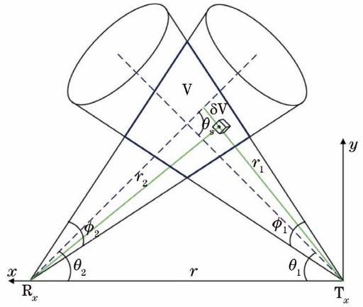
Fig. 1. NLOS UV communication model
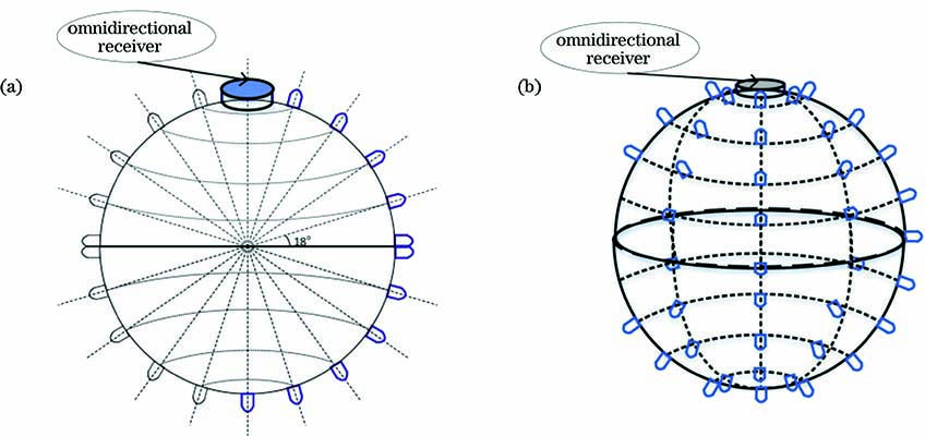
Fig. 2. UV beacon communication model. (a) Two-dimensional model; (b) three-dimensional model
Fig. 3. Communication coverage of a wireless UV beacon node in two- and three-dimensional spaces. (a) Two-dimensional space; (b) three-dimensional space
Fig. 4. Four-node positioning model
Fig. 5. Movement status of two drones
Fig. 6. Vector sharing method for collision avoidance
Fig. 7. Received signal strength of four ranging methods
Fig. 8. Received signal strength of different transmitting and receiving angles under NLOS
Fig. 9. UV ranging error at different ranging modes
Fig. 10. Positioning results of two- and three-dimensional spaces. (a) Two-dimensional space; (b) three-dimensional space
Fig. 11. 2D and 3D spatial positioning accuracy
Fig. 12. Two UAV collision avoidance paths
Fig. 13. Distance between two UAVs
|
Table 1. System model parameters

Set citation alerts for the article
Please enter your email address
© Copyright 2018-2021 | Chinese Laser Press. All Rights Reserved 沪ICP备15018463号-20