
Mehrdad Irannejad, Mustafa Yavuz, Bo Cui. Finite difference time domain study of light transmission through multihole nanostructures in metallic film[J]. Photonics Research, 2013, 1(4): 154
- Photonics Research
- Vol. 1, Issue 4, 154 (2013)
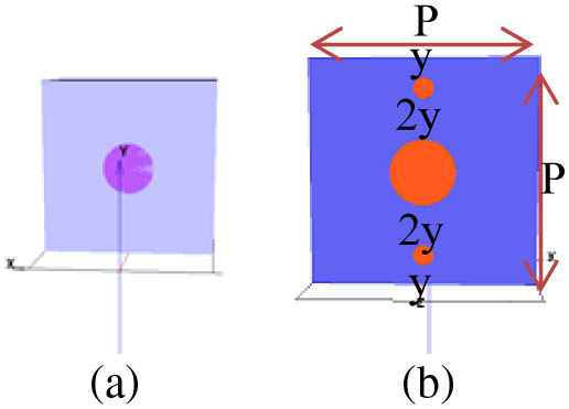
Fig. 1. Schematic diagram of the studied unit cells of infinite periodic arrays of (a) a single subwavelength hole and (b) dissimilar vertical chain holes with hole depths of 100 nm, structural period of P R
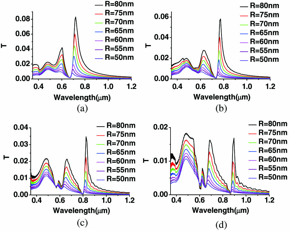
Fig. 2. FDTD calculated transmission spectrum of single-hole array of fixed hole depth of 100 nm, different hole radii in the range of 50–80 nm, and structural periodicity of (a) P = 400 nm P = 450 nm P = 500 nm P = 550 nm y
Fig. 3. Transmittance spectra of three similar hole chain array of fixed hole depth of 100 nm, hole radius of 50 nm, and different structural periodicities. The incident EM field was linearly polarized along the y
Fig. 4. Transmittance spectra of three-hole chain arrays of fixed hole depth of 100 nm, different side-hole radii, and structural periodicities of (a) P = 400 nm P = 450 nm P = 500 nm P = 550 nm y
Fig. 5. Transmittance spectra of three-hole chain arrays of fixed hole depth of 100 nm, different side-hole radii, R s P = 400 nm P = 450 nm P = 500 nm P = 550 nm x
Fig. 6. FDTD calculated electric profile of the (1,0) resonance mode of three-hole chain arrays at different incident light polarization and structural periodicities. The top row shows the electric profile of the three-hole chain array of periods of (a) 400 nm, (b) 450 nm, (c) 500 nm, and (d) 550 nm under illumination of an x y
| ||||||||||||||||||||||||||||||||||||||||||||||||||||||||||||||||||||||||||||||||
Table 1. Resonance Wavelength Position of a Square Single-Hole Array Perforated on the Silica-Supported Gold Film with Hole Radius of 50 nm, Hole Depth of 100 nm, and Different Structural Periodicitiesa
|
Table 2. Optical Transmission and Transmittance Enhancement of the (1,0) Peak of the Three-Hole Chain Array Relative to the Single-Hole Array at Different Structural Periods, R s = 25 nm R = R c = 80 nm
|
Table 3. FWHM of the (1,0) Resonance Mode of Three-Hole Chain Arrays as a Function of Vertical Distance between Holes (y a

Set citation alerts for the article
Please enter your email address
© Copyright 2018-2021 | Chinese Laser Press. All Rights Reserved 沪ICP备15018463号-20