Abstract
The optical transmittance properties of single-hole arrays and three-hole chain (vertical) arrays with different geometrical parameters were numerically investigated. It was shown that on increasing the vertical distance between the holes in the hole chain array, the FWHM of the (1,0) resonance mode was decreased and minimum FWHM of 29 nm was obtained for a vertical gap of 48 nm between each side hole. A 1.5–2.0 times larger transmittance enhancement was observed by varying the incident light polarization from the y axis to the x axis. Furthermore, it was found that the optical transmittance of the hole chain array in the case of linearly x-axis polarized incident electromagnetic (EM) field was ~6 times larger than that linearly y-axis polarized incident EM field.1. INTRODUCTION
The optical properties of subwavelength hole structures in noble metal films have been a focus of many research groups around the world since 1998, when the discovery of extraordinary optical transmission (EOT) was reported by Ebbesen et al. [1].
Based on Bethe’s [2] formulation in the subwavelength limit, i.e., , the normalized transmission for a given hole radius of and incident electromagnetic (EM) field at wavelength of is given by which predicts a rapid deduction in transmittance intensity on increasing λ.
Although, by using Eq. (1), the transmittance of a subwavelength hole with radius of 75 nm in 200 nm silver film is predicted to be of the order of , an enhanced transmission of up to 4% was obtained [1]. This enhancement in transmission of the subwavelength aperture is attributed to the coupling and decoupling between resonance evanescent waves [i.e., surface plasmons (SPs)] at the metal–dielectric interfaces and incident EM [1]. The EM field enhancement can be even greater in a nanostructure where the light is efficiently confined at the subwavelength holes. Such enhancement has allowed potential application in many different areas, such as sensing [3], integrated nano/microphotonics [4], plasmonic photolithography [5], fluorescence microscopy [6], surface enhanced Raman scattering (SERS) [7], second harmonic generation (SGH) [8], and supercontinuum generation (SCG) [9].
Sign up for Photonics Research TOC. Get the latest issue of Photonics Research delivered right to you!Sign up now
It is well known that, in the case of a normal incidence EM field, the maximum transmission wavelength of the square array at the metal–dielectric interface is given by [10] where and are the permittivities of the metal and the dielectric medium, respectively. The and are integers, and is the structural periodicity. Therefore, the transmission peak can be labeled with integers and in the optical spectra and strongly depends on the structural periodicity of the array.
To further optimize the transmission properties, notably the peak transmission and the narrow spectral linewidth (FWHM) that is critical for practical application of EOT structures, one can use more than one subwavelength hole in each unit cell. Effects of single/multi-subwavelength hole geometries, such as isolated hole arrays, chains, and array structures, have been studied by different research groups in recent years [11,12]. Gao and co-workers [11] investigated the effects of the incident EM field polarization on different subwavelength circular hole structures. Based on their investigations, on using a five-hole chain structure parallel to the electric field of the incident EM field, the propagating SP mode becomes broader, followed by a blueshift, compared to an isolated single-hole structure. However, the transmission spectra of the five-hole chain subwavelength structure, which is perpendicular to the electric field of the incident light, is very similar to the transmission spectrum of a single isolated hole, except that the electric field is localized and becomes very strong around each hole.
The transmission properties of double-hole arrays with different gap distances between the holes and different periodicities of the arrays were studied by Gordon et al. [12]. This study showed that the resonance mode of the double-hole structure is a localized effect and the maximum of the local field enhancement does not follow the structural periodicity of the array. However, the transmission intensity could be enhanced by tuning the structural periodicity of the array to the localized resonance mode of the double-hole.
The numerical analysis of optical response of nanohole arrays (NHAs) is simplified by considering the infinite and periodic structure. In this case, only EM fields within a unit cell need to be calculated [13]. Therefore, in this work, we investigate the influence of the number of subwavelength holes (single hole and three holes) in a unit cell of an infinite periodic array on the optical transmission spectra. It was reported that transmission features of NHAs depend only on the hole–hole distance, the SP mode refractive index, and the in-plane hole distribution and position [14,15], and that the crucial role in transmission enhancement is played by SP modes. It should be mentioned that on using the finite array structure, the effects of boundary conditions on the transmission spectrum become more vital than that of the periodicity.
The effects of using an incident EM field at different polarizations on the optical properties of the subwavelength hole array in a metallic thin film supported by silica substrate have also been studied to identify the optimal geometries and the incident EM field polarization to obtain high peak transmission and narrow FWHM. The narrow FWHM and high transmission intensity will increase the sensitivity of the EOT structure in sensing applications.
2. FDTD FRAMEWORK
Numerical study of subwavelength hole structures in a metallic film has been carried out by a variety of methods, such as the finite difference time domain (FDTD) method [16], the multiple-multipole method [17], and Green’s dynamic method [18]. The FDTD method is faster than the other two methods, but its applicability is sometimes limited by a requirement of small grid size to produce rapid spatial variation of EM fields at metal–dielectric interfaces.
In this work, a series of subwavelength hole structures in gold thin film supported by silica substrate were studied. The effects of varying hole radius, number of holes, and EM field polarization on the optical transmittance properties of the incident EM field through subwavelength hole square arrays were analyzed by using the 3D full wavevector FDTD method, which is a reliable method in solving Maxwell’s equations in dispersive media such as gold and silver. Each medium was specified by a relative permittivity, . For the substrate layer, permittivity was assumed to be and the Lorentz–Drude model was employed to describe the permittivity of the gold layer [19,20].
The FDTD was carried out by using the commercial software package OptiFDTD 10 from OPTIWAVE Inc. The plane wave source, subwavelength hole, and monitor were co-planar with boundary conditions that made them effectively infinite. In this study, a plane wave of linearly polarized light along the axis (, time offset of , and half-width of ) that propagates along the axis was used. The simulation background was taken as air (). The radius of the subwavelength holes was varied in the range of 50–80 nm, and the structural periodicity was in the range of 400–550 nm. The simulation cell is . The periodic boundary condition was used in the and directions and an anisotropic perfect matching layer was used in the direction as the absorbing boundary condition. The calculation grid resolution was as high as 5 nm (grid point-to-point distance) in the simulation cell. The calculation time was set to 100 fs, with calculation step size of 0.00834 fs, for a total of about 12,000 time steps per simulation. The transmission spectra were calculated using an monitor at 150 nm away from the air/film interface.
3. RESULTS AND DISCUSSION
The excited propagating SP affects the transmission spectra of the perforated subwavelength holes in a metallic film and these effects were investigated on different subwavelength hole structures, as shown in Fig. 1. The FDTD results for the transmittance spectra of different structures with fixed hole depth of 100 nm, different periodicities, and different hole radii are discussed in the following sections.
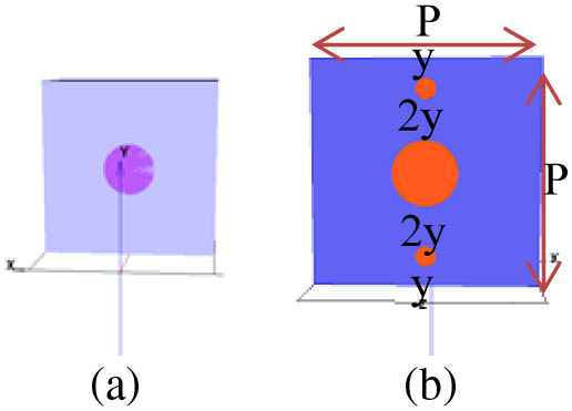
Figure 1.Schematic diagram of the studied unit cells of infinite periodic arrays of (a) a single subwavelength hole and (b) dissimilar vertical chain holes with hole depths of 100 nm, structural period of , and hole radii of .
The optical transmittance behavior of a periodic array where the unit cell of the array includes dissimilar vertical chain holes instead of a single hole is the main focus of this research. A brief review of the optical properties of a single-hole array is given in Section 3.A. In the second part of this section, the optical transmission properties of the vertical chain hole array with similar and dissimilar structures are studied. A brief comparison between these structures is also given in this section.
A. Single-Hole Array
In Fig. 2, the optical transmittance spectra of a circular single-hole array [Fig. 1(a)] of fixed hole depth of 100 nm and different hole radii in the range of 50–80 nm are compared at different structural periodicities. As can be seen in this figure, the transmission intensity was reduced upon increasing the structural periodicity in the range of 400–550 nm, and the resonance wavelength was shifted toward a longer wavelength, as reported elsewhere [15,21].

Figure 2.FDTD calculated transmission spectrum of single-hole array of fixed hole depth of 100 nm, different hole radii in the range of 50–80 nm, and structural periodicity of (a) , (b) , (c) , and (d) . The incident EM field was polarized along axis.
The maximum optical transmission intensity of 8.3% was observed at resonance wavelength of 720 nm, hole radius of 80 nm, and period of 400 nm. The major resonance peaks were attributed to the direct transmission of the light through the film surface, which is not related to the subwavelength hole array properties [22], and to the (1,0) and (1,1) resonance modes as listed in Table 1. The wavelength of (1,0) and (1,1) resonances that were given by Eq. (2) are also listed in this table. As shown in this table, there was a slight difference between the resonance wavelengths given by Eq. (2) and those obtained by the FDTD calculation. This could be attributed to interference between the SP resonance (SPR) evanescent waves with the transmitted light through the subwavelength holes [23] and phase shift due to SP scattering by air/hole and hole/substrate interfaces [24,25].
| | Resonance Wavelength (nm) |
|---|
| | | FDTD | Theory (Eq. 2) |
|---|
| | | Air/Film | Film/Sub | Air/Film | Film/Sub |
|---|
| Period | Gold Transmission | 0,1 | 1,1 | 0,1 | 1,1 | 0,1 | 1,1 | 0,1 | 1,1 |
|---|
| 400 | 480 | 370 | — | 690 | 593 | 417 | 295 | 662 | 468 |
| 450 | 480 | 363 | — | 746 | 611 | 469 | 332 | 745 | 527 |
| 500 | 480 | 581 | — | 810 | 638 | 521 | 368 | 827 | 585 |
| 550 | 480 | 615 | 371 | 877 | 669 | 573 | 405 | 910 | 643 |
Table 1. Resonance Wavelength Position of a Square Single-Hole Array Perforated on the Silica-Supported Gold Film with Hole Radius of 50 nm, Hole Depth of 100 nm, and Different Structural Periodicitiesa
B. Three-Hole Chain Array
A hole chain (vertical) array was considered as periodic structure in the plane, where each unit cell contains three holes along the axis. Since the coupling of the SPR modes of adjacent holes is sensitive to the spacing between the subwavelength holes, the vertical distance between each hole was kept constant, as shown in Fig. 1(b) (i.e., , where is the structural period, and are the central and side hole diameters, respectively. In such an arrangement [Fig. 1(b)], the location of the two side holes is not fixed, but the spacing of two adjacent holes is uniformly distributed (). In this study, the vertical and horizontal period were fixed as . Two different structures, i.e., similar () and dissimilar () hole chain arrays, were considered to study the difference between them. The central hole radius was chosen as 80 nm, and the two side-hole radii were varied in the range of 25–80 nm in the dissimilar chain array structures. The central hole radius and the side hole radii in the similar hole chain arrays were chosen to be 50 nm.
1. Three Similar Holes Chain Array
The optical transmittance spectra of chain arrays with three similar holes with differing structural periods in the range of 400–550 nm and hole radius of 50 nm are compared in Fig. 3. As can be seen from this figure, the dominant transmission peaks were attributed to intraband transition, i.e., direct transmission, of gold film, which occurs regardless of the subwavelength hole array structure [26,27]. However, no evidence of SPR peaks was observed. This is not unexpected since effectively the array periodicity along the axis is reduced to .
Figure 3.Transmittance spectra of three similar hole chain array of fixed hole depth of 100 nm, hole radius of 50 nm, and different structural periodicities. The incident EM field was linearly polarized along the axis.
2. Three Dissimilar Holes Chain Array
The optical transmittance spectra of chain arrays with three dissimilar holes of different structural periods (in the range of 400–550 nm) and different side-hole radii (in the range of 25–80 nm) are compared in Fig. 4. From this figure, it can be observed that the (1,0) resonance peak intensity was reduced on increasing the periodicity as expected in the uniform single subwavelength hole array [28]. This is due to strong confinement of the electric dipole moment at the rim of each hole. Thus, by increasing the vertical distance, the total electric field resulting from superposition of the electric fields of all vertical holes is reduced. This results in weaker coupling between the total SPR of the vertical holes and thus weaker Bragg resonance of the (1,0) mode.
Figure 4.Transmittance spectra of three-hole chain arrays of fixed hole depth of 100 nm, different side-hole radii, and structural periodicities of (a) , (b) , (c) , and (d) . The incident EM field was linearly polarized along the axis.
From Fig. 4 it is clear that, on increasing the side-hole radius and thus reducing the vertical distance between the holes (i.e., ), the EM direct transmission through the film becomes the dominant feature, while the SPR modes vanished gradually. This implies that side-hole radius well below 50 nm is desirable for SPR sensing applications.
The reduction in SPR transmission intensity could be attributed to destructive coupling of the SP modes of the central hole with the SP modes of the two sideholes, which were nearly separated [26].
The transmission intensity of the (1,0) resonance mode is increased when using a dissimilar three-hole chain structure compared to the single-hole structure, as shown in Table 2. This table also shows the optical transmittance enhancement, which is defined as the ratio of the transmittance intensity of the three-hole chain array with central hole radius of to that of the single-hole array of hole radius of (here and ). The maximum enhancement for a -polarized EM field was obtained as 1.53 at periodicity of 500 nm.
| | | Tchain | Enhancement | | Tchain | Enhancement |
|---|
| Period | Tsingle | y-axis polarized | y-axis polarized | Tsingle | x-axis polarized | x-axis polarized |
|---|
| 400 | 0.083 | 0.12 | 1.44 | 0.083 | 0.19 | 2.29 |
| 450 | 0.058 | 0.085 | 1.46 | 0.058 | 0.13 | 2.24 |
| 500 | 0.034 | 0.052 | 1.53 | 0.034 | 0.077 | 2.26 |
| 550 | 0.017 | 0.025 | 1.47 | 0.017 | 0.041 | 2.41 |
Table 2. Optical Transmission and Transmittance Enhancement of the (1,0) Peak of the Three-Hole Chain Array Relative to the Single-Hole Array at Different Structural Periods, , , and Different Incident EM Field Polarization
3. Effects of Varying the Incident EM Field Polarization.
It is known that the excitation of the localized SP (LSP) and propagating SP and their contribution to the transmission intensity of the hole chain array strongly depends on the polarization of the incident EM filed [11]. The optical transmittance intensities of a dissimilar-holes chain array of different side-hole radii for a linearly -polarized incident EM field at different structural periodicities are compared in Fig. 5. As can be seen from this figure, the transmittance intensity of the three-hole chain array was increased on increasing the radii of the two side holes compared to those with a linearly -polarized incident EM field.
Figure 5.Transmittance spectra of three-hole chain arrays of fixed hole depth of 100 nm, different side-hole radii, , and structural periodicities of (a) , (b) , (c) , and (d) . The incident EM field was linearly polarized along the axis.
This enhancement in transmission intensity for an -polarized EM field could be understood by considering the nature of the SP and LSP excitation and their contribution to the coupling with the incident EM field.
It is known that the SPR mode propagates parallel to the electric field of the incident EM field [28], and that the SPR mode couples into and out of the hole at the rim of the subwavelength hole.
In the case of a linearly polarized incident EM field, the coupling occurs between the Bragg resonance modes, which propagate along the axis, and the SPR modes, which propagate along the axis, of neighboring holes due to two different periodicities, one (along the axis) and one smaller than , i.e., , (along the axis). However, in the case of a linearly -polarized EM field, the SPRs from the hole chain array propagate along the axis where the periodicity is . Therefore, coupling of the central- and side-hole SPR modes with the Bragg resonant modes leads to such an enhancement in the transmission intensity. However, excitation of LSP and, hence, a strong localized electric field around each hole could be another reason for such enhancement in transmission intensity [11] as it is reported in Table 2.
As can be seen from this table, in the case of an -polarized incident EM field, the optical transmittance enhancement was roughly 1.5–2.0 times larger than that for -polarized incident EM field. In the case of -polarized incident EM field, the maximum enhancement was recorded as 2.41 compared to the enhancement of 1.53 for -polarized incident EM field. The maximum (minimum) transmission intensity of 62% (43%) was recorded for side-hole radius of 65 (80) nm and period of 450 (550) nm as it is evident in Fig. 5(b) [Fig. 5(d)].
The effects of varying incident EM field polarization from -polarized to -polarized on the electric field profile of the three-hole chain array of hole radii of and and different periods (in the range of 400–550 nm) are compared in Fig. 6. From this figure, it is clear that, in the case of using -polarized incident EM field, the electric field intensity, , and the dipole moment confinement of the three-hole chain array were recorded to be higher than in the case of using -polarized incident EM field. It is also clear that, upon increasing the structural periodicity from 400 to 500 nm, the electric field intensity was increased from 18 to and 23 to , respectively for -polarized and -polarized incident EM fields. However, in the three-hole chain array of period of 550 nm, the electric field intensity was recorded as 40 and , respectively, for -polarized and -polarized incident EM fields.
Figure 6.FDTD calculated electric profile of the (1,0) resonance mode of three-hole chain arrays at different incident light polarization and structural periodicities. The top row shows the electric profile of the three-hole chain array of periods of (a) 400 nm, (b) 450 nm, (c) 500 nm, and (d) 550 nm under illumination of an -polarized EM field. The bottom row is for a -polarized incident EM field and periods of (e) 400 nm, (f) 450 nm, (g) 500 nm, and (h) 550 nm.
It was found that, on increasing the side-hole radius and therefore reducing the vertical distance () between each hole in the unit cell, the FWHM of the (1,0) resonance mode was increased, as reported in Table 3. This was due to strong coupling of the SPRs of adjacent holes [11]. The minimum FWHM was calculated as small as 29 nm for a three-hole chain array of side-hole radius of 25 nm and structural periodicity of 550 nm, which is considered very desirable for SPR device applications that need high sensitivity.
| Period | Rb (nm) | y (nm) | FWHM (nm) | Rb (nm) | y (nm) | FWHM (nm) |
|---|
| 400 | 25 | 23.33 | 55 | 50 | 6.67 | 175 |
| 450 | 25 | 31.67 | 36 | 55 | 11.67 | 92 |
| 50 | 15 | 75 | 60 | 8.33 | 152 |
| 65 | 5 | 273 | — | — | — |
| 500 | 25 | 40 | 30 | 65 | 13.33 | 85 |
| 50 | 23.33 | 41 | 70 | 10 | 121 |
| 55 | 20 | 48 | 75 | 6.67 | 195 |
| 60 | 16.67 | 62 | 80 | — | — |
| 550 | 25 | 48.33 | 29 | 65 | 21.67 | 40 |
| 50 | 31.67 | 33 | 70 | 18.33 | 50 |
| 55 | 28.33 | 35 | 75 | 15 | 72 |
| 60 | 25 | 37 | 80 | 11.67 | 101 |
Table 3. FWHM of the (1,0) Resonance Mode of Three-Hole Chain Arrays as a Function of Vertical Distance between Holes () at Different Structural Periodsa
4. CONCLUSION
The optical transmittance properties of chain arrays with similar and dissimilar holes were investigated. Although no SPR transmission peaks were observed in the similar-hole chain array, the SPR was the dominant transmission peak in the dissimilar-hole structure. It was shown that, on reducing the vertical distance between the holes in the dissimilar structure, the linewidth of the (1,0) mode was increased. In addition, an times larger optical transmission was recorded on varying the incident EM field polarization from the axis to the axis. Using array with multiple dissimilar holes that provides larger transmission intensity and narrower linewidth suggests promising applications in biosensing and nanophotonics applications, such as nano-optical bandpass filters and nano-optical switching.
References
[1] T. W. Ebbesen, H. J. Lezec, H. F. Ghaemi, T. Thio, P. A. Wolff. Extraordinary optical transmission through sub-wavelength hole arrays. Nature, 391, 667-669(1998).
[2] H. A. Bethe. Theory of diffraction by small holes. Phys. Rev., 66, 163-182(1944).
[3] C. Guan, Y. Wang, L. Yuan. Multi-hole optical fiber surface plasmon resonance sensor. J. Phys., 276, 012507(2011).
[4] J. V. Coe, S. M. Williams, K. R. Rodriguez, S. Teeters-Kennedy, A. Sudnitsyn, F. Hrovat. Extraordinary IR transmission with metallic arrays of subwavelength holes. Anal. Chem., 78, 1384-1390(2006).
[5] X. Luo, T. Ishihara. Subwavelength photolithography based on surface-plasmon polariton resonance. Opt. Express, 12, 3055-3065(2004).
[6] S. H. Garrett, L. H. Smith, W. L. Barnes. Fluorescence in the presence of metallic hole arrays. J. Mod. Opt., 52, 1105-1122(2005).
[7] S. I. Bozhevolnyi, J. Beermann, V. Coello. Direct observation of localized second-harmonic enhancement in random metal nanostructures. Phys. Rev. Lett., 90, 197403(2003).
[8] M. Moskovits. Surface-enhanced spectroscopy. Rev. Mod. Phys., 57, 783-826(1985).
[9] P. Mühlschlegel, H.-J. Eisler, O. J. F. Martin, B. Hecht, D. W. Pohl. Resonant optical antennas. Science, 308, 1607-1609(2005).
[10] H. F. Ghaemi, T. Thio, D. E. Grupp, T. W. Ebbesen, H. J. Lezec. Surface plasmons enhance optical transmission through subwavelength holes. Phys. Rev. B, 58, 6779-6782(1998).
[11] F. Gao, J. Zhao, D. Qi, Q. Hu, R. Zhang, R. Peng. Excitation of surface plasmons in subwavelength nanoaperatures with different geometries. J. Nanosci. Nanotechnol., 10, 7324-7327(2010).
[12] R. Gordon, D. Sinton, K. L. Kavanagh, A. G. Brolo. A new generation of sensors based on extraordinary optical transmission. Acc. Chem. Res., 41, 1049-1057(2008).
[13] F. J. Garcia-Vidal, L. Martin-Moreno, T. W. Ebbesen, L. Kuipers. Light passing through subwavelength apertures. Rev. Mod. Phys., 82, 729-787(2010).
[14] D. Pacifici, H. J. Lezec, L. A. Sweatlock, R. J. Walters, H. A. Atwater. Universal optical transmission features in periodic and quasiperiodic hole arrays. Optics Express, 16, 9222-9238(2008).
[15] H. Ahmadreza, K. Mojtaba, T. Vo-Van. Optical behaviour of thick gold and silver films with periodic circular nanohole arrays. J. Phys. D, 45, 485105(2012).
[16] S.-H. Chang, S. Gray, G. Schatz. Surface plasmon generation and light transmission by isolated nanoholes and arrays of nanoholes in thin metal films. Opt. Express, 13, 3150-3165(2005).
[17] R. Wannemacher. Plasmon-supported transmission of light through nanometric holes in metallic thin films. Opt. Commun., 195, 107-118(2001).
[18] G. C. des Francs, D. Molenda, U. C. Fischer, A. Naber. Enhanced light confinement in a triangular aperture: experimental evidence and numerical calculations. Phys. Rev. B, 72, 165111(2005).
[19] V. Alexandre, L. Thierry. Description of dispersion properties of metals by means of the critical points model and application to the study of resonant structures using the FDTD method. J. Phys. D, 40, 7152-7158(2007).
[20] A. D. Rakic, A. B. Djurisic, J. M. Elazar, M. L. Majewski. Optical properties of metallic films for vertical-cavity optoelectronic eevices. Appl. Opt., 37, 5271-5283(1998).
[21] E. Laux, C. Genet, T. W. Ebbesen. Enhanced optical transmission at the cutoff transition. Opt. Express, 17, 6920-6930(2009).
[22] J. M. McMahon, J. Henzie, T. W. Odom, G. C. Schatz, S. K. Gray. Tailoring the sensing capabilities of nanohole arrays in gold films with Rayleigh anomaly-surface plasmon polaritons. Opt. Express, 15, 18119-18129(2007).
[23] M. Najiminaini, F. Vasefi, B. Kaminska, J. J. L. Carson. Effect of surface plasmon energy matching on the sensing capability of metallic nano-hole arrays. Appl. Phys. Lett., 100, 063110(2012).
[24] H. Liu, P. Lalanne. Microscopic theory of the extraordinary optical transmission. Nature, 452, 728-731(2008).
[25] J.-Y. Li, Y.-L. Hua, J.-X. Fu, Z.-Y. Li. Influence of hole geometry and lattice constant on extraordinary optical transmission through subwavelength hole arrays in metal films. J. Appl. Phys., 107, 073101(2010).
[26] H. Gao, J. Henzie, T. W. Odom. Direct evidence for surface plasmon-mediated enhanced light transmission through metallic nanohole arrays. Nano Lett., 6, 2104-2108(2006).
[27] M. Irannejad, B. Cui. Effects of refractive index variations on the optical transmittance spectral properties of the nano-hole arrays. Plasmonics, 8, 1245-1251(2013).
[28] H. Reather. Surface Plasmons(1998).


