
Tianxiao Xiao, Suo Tu, Suzhe Liang, Renjun Guo, Ting Tian, Peter Müller-Buschbaum. Solar cell-based hybrid energy harvesters towards sustainability[J]. Opto-Electronic Science, 2023, 2(6): 230011
- Opto-Electronic Science
- Vol. 2, Issue 6, 230011 (2023)
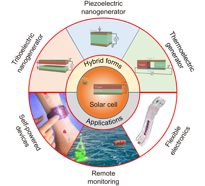
Fig. 1. Outline illustration of the review of SCHEHs.
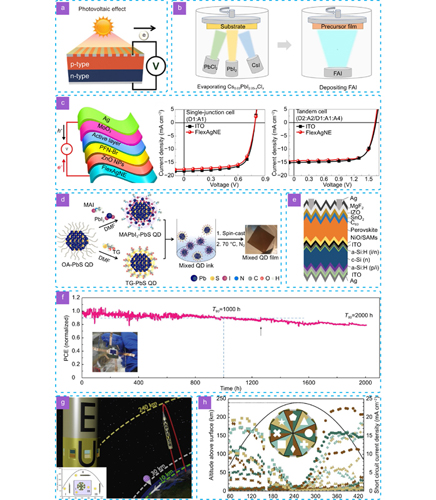
Fig. 2. Photovoltaic effect-based energy harvester. (a ) Schematic illustration of the photovoltaic effect-based energy harvester44. (b ) Simplified scheme presenting the Cl-containing alloy-mediated sequential vacuum deposition approach65. (c ) Schematic architecture of the flexible OSCs (left), J-V curves of a typical single-junction device (D1:A1) based on FlexAgNEs and ITO glass electrodes (middle), J-V curves of a typical tandem device (D2:A2/D1:A1:A4) based on FlexAgNEs and ITO electrodes (right)66. (d ) Scheme of the solution ligand exchange process67. (e ) Schematic diagram of perovskite/SHJ tandem solar cell69. (f ) Maximum power point tracking of encapsulated tandem solar cells in air. Inset is the photograph of the encapsulated device69. (g ) Schematic overview of the MAPHEUS-8 sounding rocket flight. Inset is the different illumination states70. (h ) Scatter plot showing the Jsc evolution and flight-altitude (black line) during micro-gravity70. Figure reproduced with permission from: (a) ref.44, Copyright © 2019 John Wiley and Sons; (b) ref.65, Copyright © 2022 AAAS; (c) ref.66, Copyright © 2019 Springer Nature; (d) ref.67, under a Creative Commons Attribution 4.0 International License; (e, f) ref.69, Copyright © 2023 John Wiley and Sons. (g, h) ref.70, Copyright © 2020 Elsevier.
Fig. 3. Triboelectric effect-based energy harvester. (a ) Schematic illustration of the triboelectric effect-based nanogenerator44. (b ) Variation of current and power of the TENG-flag with external load resistances and the output performances of the TENG-flag (the woven unit is 1.5 × 1.5 cm2, and the degree of tightness is 1.09) at a 22 m s-1 wind speed78. (c ) Voltage profiles of the button battery charged by TENG-flag and galvanostatically discharged at 1 μA78. (d ) Schematic diagram of the spherical TENG with spring-assisted multilayered structure floating on water, and schematic representation enlarged structure for the zigzag multilayered TENG with five basic units79. (e ) Schematic diagram of the folded elastic strip-based TENG80. (f ) Schematic diagram (left) and photographs (middle) of the wearable all-fiber TENG, as well as hundreds of LEDs powered by the TENG81. Figure reproduced with permission from: (a) ref.44, Copyright © 2019 John Wiley and Sons; (b, c) ref.78, Copyright © 2016 American Chemical Society; (d) ref. 79, Copyright © 2018 John Wiley and Sons; (e) ref.80, Copyright © 2015 American Chemical Society; (f) ref. 81, Copyright © 2015 Elsevier.
Fig. 4. Piezoelectric effect-based energy harvester. (a ) Schematic illustration of the piezoelectric effect-based nanogenerator44. (b ) Schematic structure (left), output voltage (middle), and output current (right) of the lateral-nanowire-array integrated nanogenerator85. (c ) Schematic diagram of the fabrication process (left) and the photograph (right) of a high-efficient, flexible, and large-area PZT thin film-based NG using the LLO method86. (d ) Schematic images (left and middle) and the corresponding output voltage (right) of the flexible nanogenerator under the finger movement87. (e ) Fabrication process (left), SEM image (top), and output current (bottom) of the piezoelectric PVDF nanogenerator88. (f ) SEM image and the schematic structure of the PZT-PDMS energy harvester89. Figure reproduced with permission from: (a) ref.44, Copyright © 2019 John Wiley and Sons; (b) ref.85, Copyright © 2010 Springer Nature; (c) ref. 86, Copyright © 2014 John Wiley and Sons. (d) ref.87, Copyright © 2015 Elsevier. (e) ref. 88, Copyright © 2010 American Chemical Society. (f) ref. 89, Copyright © 2018 American Chemical Society.
Fig. 5. Thermoelectric effect-based energy harvester. (a ) Schematic illustration of the thermoelectric effect-based generator44. (b ) Practical TE generators connecting large numbers of junctions in series to increase operating voltage and spread heat flow23. (c ) Honda prototype TEG exhaust heat recovery system97. (d ) Schematic illustration (left) and photographs (right) of the complete TEG device on pipe98. (e ) Structure of the proposed lateral Y type FTEGs101. (f ) Practical applications of the fabricated dual-functional sensor as electronic skins103. (g ) Sketch of the sample preparation of a solution-processable all-polymer TEG110. (h ) Performances (left), as well as photographs of the undoped (top) and 40 wt% doped (bottom) thin-film TEGs110. Figure reproduced with permission from: (a) ref.44, Copyright © 2019 John Wiley and Sons; (b) ref. 23, Copyright © 2008 AAAS; (c) ref. 97, Copyright © 2016 Elsevier; (d) ref. 98, Copyright © 2017 Elsevier; (e) ref. 101, Copyright © 2018 Elsevier. (f) ref. 103, under a Creative Commons Attribution 4.0 International License. (g, h) ref.110, Copyright © 2020 John Wiley and Sons.
Fig. 6. SCHEHs based on solar cell and triboelectric nanogenerator. (a ) Schematic illustration and the photograph of the hybrid energy harvester112. (b ) Architecture of the hybrid TENG/Si tandem solar cell113. (c ) Schematic illustration of the flexible hybrid energy harvesting system114. (d ) Scheme of the configuration of the TENG fabrics and the fiber-shaped dye-sensitized solar cell (top), as well as output current of the hybrid energy-harvesting device115. (e ) Schematic illustration (left) and the working principle (right) of the raindrop-solar hybrid energy harvester with embedded charge-storage layer116. (f ) Photographs and the schematic illustration of the synergistic solar and raindrop hybrid energy harvester117. (g ) Schematic diagram of the multifunctional hybrid device118. (h ) Schematic illustration of the self-powered environmental visualized system (left), and alterable colored LED showing different light at different environment (right)118. Figure reproduced with permission from: (a) ref.112, Copyright © 2018 American Chemical Society; (b) ref. 113, Copyright © 2021 Elsevier; (c) ref. 114, Copyright © 2020 Elsevier. (d) ref. 115, Copyright © 2016 John Wiley and Sons. (e) ref. 116, Copyright © 2022 Elsevier; (f) ref. 117, Copyright © 2022 Elsevier; (g, h) ref. 118, Copyright © 2021 Elsevier.
Fig. 7. SCHEHs based on solar cell and piezoelectric nanogenerator. (a ) Schematic structure of a serially integrated hybrid cell119. (b ) Schematic illustration of a compact hybrid cell120. (c ) Schematic illustration (left) and the photograph (right) of the tree shaped hybrid nanogenerator121. (d ) Output voltage of the hybrid cell when the pressure is applied periodically at an interval of 3.0 s for an extended period of 1.0 s122. (e ) Schematic illustration of a composite photovoltaic/PENG film123. (f ) Output performance (left) and schematic illustration (middle and right) of the hybrid device with the bending instrument124. (g ) Experimental configuration of the parallel hybrid power system125. Figure reproduced with permission from: (a) ref.119, Copyright © 2009 American Chemical Society; (b) ref. 120, Copyright © 2011 John Wiley and Sons; (c) ref. 121, under a Creative Commons Attribution 4.0 International License; (d) ref.122, Copyright © 2015 Elsevier; (e) ref.123, Copyright © 2020 Springer Nature; (f) ref.124, Copyright © 2022 Springer Nature; (g) ref.125, Copyright © 2021 Springer Nature.
Fig. 8. SCHEHs based on solar cell and thermoelectric generator. (a ) Schematic of the PV-TE hybrid power system128. (b ) Hybrid system efficiency vs. cutoff wavelength for different concentration ratio (h = 10000 W/m2 K-1)127. (c ) Comparison of the efficiency between the PV-only system and the PV-TE hybrid system127. (d ) Schematic illustration of the hybrid generation system129. (e ) Schematic illustration (left), and electron energy band diagram of the PSC-TE hybrid device130. (f ) Schematic cross section of ZnO nanowires/CIGS solar cell connected to the thermoelectric generator131. (g ) Schematic illustration of the photovoltaic-thermoelectric hybrid device (left), and best performed J-V curves (symbol-line) and output power (dash-line) of the PSC/TE hybrid devices tested with the assisted cooling system or not (right)132. ref.132, Copyright © 2017 Elsevier. ( h ) Non-contact reflection geometry (left), non-contact transmission geometry (middle), and contact transmission geometry (right)134. (i ) Calculated TEG efficiencies for the PV-TEG hybrid system in the three different geometries134. Figure reproduced with permission from: (a) ref.128, Copyright © 2014 Elsevier; (b, c) ref. 127, Copyright © 2012 Elsevier; (d) ref. 129, Copyright © 2013 Elsevier; (e) ref. 130, Copyright © 2018 John Wiley and Sons; (f) ref. 131, Copyright © 2015 John Wiley and Sons; (g–i) ref. 134, Copyright © 2021 Royal Society of Chemistry.
|
Table 1. Comparison of the different types of SCHEHs.

Set citation alerts for the article
Please enter your email address
© Copyright 2018-2021 | Chinese Laser Press. All Rights Reserved 沪ICP备15018463号-20