Tianxiao Xiao, Suo Tu, Suzhe Liang, Renjun Guo, Ting Tian, Peter Müller-Buschbaum. Solar cell-based hybrid energy harvesters towards sustainability[J]. Opto-Electronic Science, 2023, 2(6): 230011
Copy Citation Text
Energy harvesting plays a crucial role in modern society. In the past years, solar energy, owing to its renewable, green, and infinite attributes, has attracted increasing attention across a broad range of applications from small-scale wearable electronics to large-scale energy powering. However, the utility of solar cells in providing a stable power supply for various electrical appliances in practical applications is restricted by weather conditions. To address this issue, researchers have made many efforts to integrate solar cells with other types of energy harvesters, thus developing hybrid energy harvesters (HEHs), which can harvest energy from the ambient environment via different working mechanisms. In this review, four categories of energy harvesters including solar cells, triboelectric nanogenerators (TENGs), piezoelectric nanogenerators (PENGs), and thermoelectric generators (TEGs) are introduced. In addition, we systematically summarize the recent progress in solar cell-based hybrid energy harvesters (SCHEHs) with a focus on their structure designs and the corresponding applications. Three hybridization designs through unique combinations of TENG, PENG, and TEG with solar cells are elaborated in detail. Finally, the main challenges and perspectives for the future development of SCHEHs are discussed.
The energy crisis in modern social life includes the increasingly urgent challenges of energy availability, affordability, and sustainability, which calls for a crucial transition from fossil fuels to cleaner and more renewable energy sources. Energy harvesting offers a multitude of advantages, such as sustainability, decreased reliance on external power sources, cost savings, environmental benefits, energy efficiency, versatility, and scalability. Thus, its crucial role in modern society is rooted in its potential capability to provide clean, decentralized, and dependable power solutions across a diverse range of applications, thereby contributing to a more sustainable future1-3. As traditional energy sources have limitations on reserves and environmental protection, renewable energy sources have become a focus of research and development efforts4-7. Renewable energy harvesters are considered devices, which can collect energy to generate electricity without harmful pollution from various environmental sources, such as wind8, 9, solar10-13, human motions14-18, water waves19-21, and waste heat22, 23. Among other counterparts, solar cells due to their numerous benefits, including low maintenance costs, low carbon footprints, and the abundant sources have been widely adopted as one of the most promising candidates24-26. In recent years, different types of solar cells have been fabricated for powering devices from small-scale electronics to large-scale networks and proved to be a reliable and sustainable energy harvesting technology, with the potential to significantly contribute to the global energy supply27-34.
With the rapid development, the power conversion efficiency (PCE) and operational stability of solar cells have been extensively researched and continually improved35-42. However, only a high PCE cannot resolve the main issue of solar cells in providing a stable power supply due to the weather conditions43. It means that solar cells are highly dependent on the availability of the sunlight, and the performance is obviously affected by weather conditions such as cloudy or rainy days. To overcome this limitation, integrating solar cells with other kinds of energy harvesting techniques to offer more reliable, continuous and stable electricity is in high demand44-48.
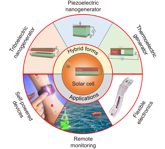
There are some newly arising energy harvesting systems, among which triboelectric nanogenerators (TENGs)49, 50, piezoelectric nanogenerators (PENGs)51, and thermoelectric generators (TEGs)52 are considered representative examples. Up to now, researchers have explored different approaches to hybridizing solar cells with these kinds of energy harvesters to create hybrid energy harvesters that can harness energy from the ambient environment via different working mechanisms53-61. Leveraging the complementary strengths of each energy harvesting technology, the hybridization of solar cells with TENGs, PENGs, and TEGs, has shown great potential in producing more stable power supplies for various applications (Fig. 1). Here, we summarize some progress of solar cell-based hybrid energy harvesters (SCHEHs) in recent years. This review begins with shortly introducing the working principles and achievements of solar cells, TENGs, PENGs and TEGs. Following that, the structural designs of SCHEHs are presented in detail with their functions and applications. At last, the challenges faced in the development of SCHEHs are discussed, and perspectives on future advancement are provided.
Figure 1.Outline illustration of the review of SCHEHs.
Photovoltaic cells also known as solar cells are a type of energy harvester that can directly convert infinite solar energy into electricity by the photovoltaic effect, and the working principle of a typical solar cell is schematically shown in Fig. 2(a)62. When the solar cell is exposed to sunlight, the semiconductor in the solar cell absorbs the light energy, which creates electron-hole pairs. These charges are then transported to the electrodes, leading to a flow of electricity63, 64. Here, the work function of the p-type semiconductor, n-type semiconductor, and electrodes is crucial for efficient charge transport and voltage generation. Therefore, achieving high energy conversion efficiency for a solar cell necessitates developing new materials and modifying their work function. The PCE of a solar cell is evaluated by
where Pmax stands for the maximum output performance, Pin represents the input solar energy, Voc is the open-circuit voltage, Jsc means the short-circuit current density, and FF is the fill factor. Here, the FF, which is defined as the ratio of the maximum power from the solar cell to the product of Voc and Jsc , is measured by the I-V scan.
Over the recent years, a large variety of solar cells based on diverse novel materials have been successfully fabricated via various deposition methods besides the traditionally well commercialized silicon solar cells and the rather well developed class of thin film solar cells. These promising next generation solar cells comprise perovskite solar cells (PSCs), organic solar cells (OSCs) and quantum dot solar cells (QDSCs). For example, Li et al. developed a chlorine (Cl)-alloy-mediated sequential vacuum deposition method for fabricating high-efficiency PSCs65. In this work, cesium iodide (CsI), lead iodide (PbI2), and lead chloride (PbCl2) were all evaporated to create a composite precursor film, which was followed by the precisely controlled deposition of formamidinium iodide (FAI) molecules (Fig. 2(b)). By utilizing this method, perovskite films with high crystallinity and homogeneity were obtained. The 1-cm2 area PSC exhibited a champion PCE of 23.44% with the certified PCE of 22.6%. In case of OSCs, a new method for creating flexible transparent electrodes (FlexAgNEs) with high performance by using a water-based homogeneous suspension of silver nanowires (AgNWs) and poly(sodium 4-styrenesulfonate) (PSSNa) as a polyelectrolyte was presented by Sun and coauthors66. Their approach relied on the ionic electrostatic charge repulsion between the AgNWs originating from the preferred adsorption of PSSNa anions, which resulted in stable and uniform AgNWs suspensions. Combining the benefits of dry and wet methods and requiring no post-treatment, with FlexAgNEs the fabricated OSC devices exhibited high performance with single-junction cells achieving the best PCE of 13.15% and tandem achieving the best PCE of 16.55%, respectively (Fig. 2(c)). For QDSCs, a mixed-QD ink method, which could improve charge carrier extraction in the light harvesting layer of the QD solar cell was proposed by Yang et al. (Fig. 2(d))67. This mixed-QD ink method was based on the formation of a mixture of donor and acceptor QDs, and each of them retained its unique chemical properties when combined in the solution phase and finally formed into a film. At last, they utilized this mixed-QD ink method to fabricate the first mixed-QD ink solar cell and achieved a PCE of 10.4%, which was two times as high as the output performance of previously reported bulk heterojunction (BHJ) QD devices68. In addition, Luo et al. reported that the crystallization of wide-bandgap perovskite films could be well controlled via an anion-engineered additive method69. This anion-engineered additive method has multiple functions, which could improve the film crystallinity, decrease the trap density, and conformably deposit on industrially textured silicon (Si). The schematic diagram of the fabricated perovskite/Si heterojunction tandem solar cell is illustrated in Fig. 2(e), and a PCE of 28.6% (certified 27.9%, 1 cm2) was obtained by this strategy. Moreover, a large-area PCE of 25.1% of the fabricated tandem solar cells for an area of 16 cm2 was achieved, making it suitable for the scalable production of tandem solar cells. Furthermore, the wide-bandgap PSCs' operating stability was greatly enhanced by using this anion-engineered additive method, and the encapsulated tandem solar cells maintained more than 80% of their initial output performance after 2000 hours of operation under the 1-sun illumination in the ambient environment (Fig. 2(f)). Besides improving the PCE and working stability, real applications of solar cells have also been focused on by researchers in recent years. For example, Reb and coworkers reported an experiment, which was applied during a suborbital rocket flight (Fig. 2(g))70. In this work, the output characteristics of PSCs and OSCs were investigated under two different phases (i. strong solar irradiance; ii. faint scattered light from the Earth). As their results shown in Fig. 2(h), both PSCs and OSCs could reach their performance expectations when exposed to space conditions, which demonstrated their potential long-term applications in future satellite missions.
Triboelectric effect-based nanogenerator
The triboelectric effect-based nanogenerator called TENG is a newly arising technology that can convert ambient mechanical energy/triggering into electricity71. It originates from Maxwell’s displacement current and is based on the coupling effect of triboelectrification and electrostatic induction during the periodic relative contact-separation motion of the surfaces of two materials72. The amount of electricity generated by TENG is strongly affected by the surface charge density, as illustrated in Fig. 3(a). The polarity of the surface charges, which is developed on materials, is determined by the triboelectric series, and these charges cause electric flow through the external circuit with specific potential differences73. The transfer process of a charge across the interface of two different materials appears when they come into contact, resulting in the generation of opposite charges on the surfaces of two materials. The relative motion of the two triboelectric materials causes the flow of electric charges between two electrodes after the generation of surface triboelectric charges in order to maintain the electrostatic equilibrium. The triboelectric potential Vtri can be expressed by the function
in which ρtri stands for the triboelectric charge density, d represents the gap distance between two triboelectric materials, and ε0 is donated as the vacuum permittivity. The triboelectric current Itri can be derived as
where Ctri stands for the capacitance between two triboelectric materials and Vtri represents the generated triboelectric potential across the two electrodes. In contrast to the conventional electromagnetic generator (EMG) for mechanical energy harvesting, TENG has a high conversion efficiency at low-frequency ranges and has the advantages of a lightweight, easy fabrication, low costs, diverse choices of materials and high durability for long-term operations74-76. Four basic working modes of TENGs are known, including vertical contact-separation (CS) mode, lateral-sliding (LS) mode, single-electrode (SE) mode, and freestanding triboelectric-layer (FT) mode77. A typical CS-mode TENG consists of several layers, including two electrodes attached on the top and bottom as well as a pair of dielectric materials serving as triboelectric surfaces in between, such as polytetrafluoroethylene (PTFE), polyvinylidene difluoride (PVDF), polydimethylsiloxane (PDMS), and polyimide (PI), etc.
After TENG was first invented by Zhong Lin Wang in 2012, various kinds of TENG-based energy harvesters have been reported for harnessing the energy from mechanical motions. For example, Zhao et al. designed a freestanding flag-type woven TENG for harvesting the wind energy from arbitrary directions by the interlaced interactions between Kapton film and a conductive cloth under wind-introduced fluttering of the flag78. At the wind speed of 22 m s−1, their fabricated device could obtain the maximum output power peak density of 135 mW kg−1 at the matched resistance of 6.5 MΩ (Fig. 3(b)). Figure 3(c) shows the fabricated woven TENG successfully powered the wireless temperature and humidity sensor node to work for more than 10 h after the 4.8-hour charging process. Xiao and coauthors utilized the TENG technology to scavenge water wave energy with the spring-assisted multilayered structure79. In their study, the water waves were generated by using a series of wave pumps, which were controlled by a function generator, and each of their fabricated devices generated a maximum output power peak of 7.96 mW at 1.0 Hz water waves (Fig. 3(d)). Finally, the TENG array consisting of four optimized TENG spherical units connected in parallel was fabricated, which produced 15.97 mW and lighted up dozens of light-emitting diodes (LEDs). Meanwhile, the TENG technology is also widely utilized in harnessing the energy from human motions. Figure 3(e) shows that a folded elastic strip-based TENG for collecting the energy from human motions was proposed by Kang and coauthors80. With the optimization of strip width, deformation frequency, and amplitude, the output current, output voltage, and output power peak reached up to 55 µA, 840 V, and 7.33 mW, respectively. Huang et al. also fabricated a high-performance, wearable all-fiber TENG-based insole81. In this work, the surface of the nanofibers was roughened with secondary nanostructure to enhance the output performance. The maximum output voltage, output current, and output power peak of the TENG-based insole reached 210 V, 45 µA, and 2.1 mW, respectively. Thus, with the advantages of soft texture, good flexibility and lightweight, this TENG-based insole ensured a maximum comfort for the wearer, and it could convert mechanical energy to successfully light up 214 LEDs connected in series by the stepping force of the human (Fig. 3(f)).
Piezoelectric effect-based nanogenerator
Besides TENG, PENG is another widely used technology to convert mechanical energy into electricity82. The first PENG was presented by Zhong Lin Wang in 200651. It was designed with a single zinc oxide (ZnO) NW bonded horizontally on a flexible substrate in 200883. The piezoelectric effect is the property of certain materials to generate electricity in response to the applied mechanical stress or strain. The working mechanism of the PENG can be described as a transient flow of electrons driven by the piezopotential, which is schematically illustrated in Fig. 4(a). When the external force is applied to the PENG, the center of the cations and anions are relatively displaced, which results in a piezoelectric potential difference between the ends and creates a new balance state. Once electrodes are connected to the external circuit, the generated piezopotential will drive the electrons to flow across the external circuit to generate electricity. Upon releasing the pressure, the electrons will flow back to return to the initial state84. The piezoelectric polarization charge density ρpie can be expressed by
in which ρpie represents the polarization charge density, dpie stands for the piezoelectric coefficient, and Х is donated as the applied stress. Meanwhile, the electric field and potential can be calculated by the charge density
in which
E stands for the divergence of the electric field, and ε represents the permittivity. Therefore, the optimized design of the piezoelectric material and device structure are significant for the output performance of the PENG. A typical PENG consists of several layers, including a top electrode, a bottom electrode, and an insulator piezoelectric material layer, such as lead zirconate titanate (PZT), barium titanate (BaTiO3), ZnO, and poly(vinylidene fluoride) (PVDF) as well as their copolymers.
Since the birth of the PENG concept, it has experienced a period of rapid development in the mechanical energy-harnessing research field. Xu et al. developed a flexible PENG based on multi-layer/multi-row alternators by integrated with vertical/horizontal ZnO NWs arrays. In their work, the ZnO NWs were strong enough to avoid mechanical deformation, and the entire PENG device demonstrated exceptional flexibility85. A maximum output voltage of 1.26 V, and a maximum output current of 28.8 nA was attained when the device was periodically bent and released. This maximum output voltage of 1.26 V was close to the voltage of conventional electrical devices (Fig. 4(b)). Meanwhile, a high-efficiency, lightweight, and large-area PZT thin-film-based PENG was successfully fabricated by Park and coauthors via utilizing the laser lift-off (LLO) process on the plastic substrate86. As shown in Fig. 4(c), by adopting this LLO method, the entire area of the PZT thin film could be transferred onto a flexible plastic substrate without causing any structural damage. During periodic bending-releasing motions, the output voltage of 200 V and the output current density of 150 µA cm−2 could be generated by the PZT-based PENG, respectively. Zhang et al. used the spinning method to fabricate super flexible BaTiO3-polyvinyl chloride (PVC) composite NWs for stretchable PENG devices87. In this work, the synthesis of BaTiO3 nanowires with <001> orientation was accomplished by a topochemical method. The reported output voltage and output current could reach 0.9 V and 10.5 nA respectively under the finger movement ( Fig. 4(d)). Besides BiTiO3, the spinning electrospinning method combining direct-write, mechanical stretching, and in-situ electrical poling was also applied on PVDF NWs to successfully fabricate a flexible PENG by Chang and coauthors88. In their work, dipoles in the PVDF NW crystal were naturally aligned by the strong electric fields and stretching forces from the electrospinning process, leading to the transformation of the nonpolar α-phase into the polar β-phase. Under periodic long-term reliability tests, a single PVDF NW-based PENG's output performance was relatively stable without obvious degradation, demonstrating the stability of their fabricated PENG (Fig. 4(e)). In Fig. 4(f), Zhang and coauthors designed a flexible PENG by bonding the PZT NWs with a PDMS polymer89. In their work, PZT NWs with a diameter of 100 nm and a length of 6 µm were synthesized via a facile hydrothermal process. The output voltage of 2.7 V, and the output power peak density of 51.8 µW cm−3 with a matched external load resistance of 2 MΩ could be achieved at the frequency of 25.2 Hz. This PZT-based PENG could output 8 times more power than previously reported BaTiO3-based PENG.
Thermoelectric effect-based generator
Unlike the piezoelectric effect, which is a property of specific materials that generate an electric charge when subjected to mechanical stress or strain, the thermoelectric effect is a phenomenon where the application of a temperature gradient across specific materials leads to the generation of an electric voltage. It is based on the Seebeck effect, which establishes that when there exists a temperature difference between two ends of a material with different electrical conductivity, an electric potential is induced. This effect is reversible, enabling the creation of a temperature difference by passing an electric current through the material, known as the Peltier effect90, 91. Figure 5(a) shows the direct and efficient conversion between thermal energy and electricity based on the Seebeck effect. It is hence considered a sustainable alternative towards the re-utilization of heat sources for future energy supply92. A thermoelectric material is commonly quantified by using the nondimensional figure-of-merit (ZT) of the thermoelectric material
in which S stands for the material-specific Seebeck coefficient, σ represents the electrical conductivity, κ is denoted as the thermal conductivity (including electronic κel and phononic κph contributions), Thot (K) is the hot-side temperature, and Tcold (K) is the cold-side temperature93. An ideal TEG efficiency, ηTEG, can be written as a function of the temperatures and the ZT, which is illustrated as follows94
In contrast to conventional heat engines utilizing the working fluid to convert thermal energy to kinetic energy, the TEG, which can directly convert heat energy into electricity by utilizing the unique “working fluid” of charge carriers (holes or electrons, shown in Fig. 5(b)), has emerged as another environmental-friendly solution with merits of zero-emission, no circulating liquid or gas, no moving parts, silence, scalability and durability in recent years.
Currently, a major driving force for TEG’s application is in automotive and industrial waste heat recovery to achieve resource reuse95. Because the efficiency of automobiles is less than 30%, and more than 2/3 of energy is directly dissipated as waste heat to the environment through the exhaust pipe and the radiator96. For example, in a recent work, Honda company demonstrated a proof-of-concept prototype (Figure 5(c)) with a maximum of approximately 500 W for automotive waste heat recovery97. They used a simple design of a thin flat rectangular box with TEGs placed on the top and bottom surfaces of the exhaust pipe and claimed a fuel consumption reduction of around 3%. Iezzi et al. demonstrated a flexible planar TEG, which could extract heat from industrial heat pipes to power a wireless sensor network98. The proposed module of 420 Ag/nickel (Ni) thermocouples were prepared on a flexible substrate in order to match the cylindrical form of the pipe (Fig. 5(d)). Their TEG generated an output power of 308 μW at the temperature gradient of 127 K. Meanwhile, TEGs that use thermal energy generated by the human body as a constant heat source are also well-appropriate for a wide variety of wearable and biomedical electronics within the nW to mW power range due to permanent direct current (DC) output99, 100. Trung et al. fabricated a flexible TEG by using an electrochemical deposition process to synthesize thermoelectric materials including bismuth telluride (Bi2Te3) and antimony telluride (Sb2Te3)101. In their work, a novel idea of lateral Y-type TEG instead of conventional vertical π-type TEG was proposed to enhance the output performance of temperature energy harvesting. Fig. 5(e) shows that with the temperature difference of 22 °C between the human body and the ambient environment, the fabricated TEG device could generate approximately 3 mW cm−2 of output power density. Organic thermoelectrics exhibit potential for wearable heating and cooling devices, and near-room-temperature energy generation102. Zhang and coworkers reported a flexible temperature-pressure dual-parameter sensor by casting conductive polymer poly(3,4-ethylenedioxythiophene): poly(styrenesulfonate) (PEDOT:PSS) on a microstructured polyurethane (PU) foam via a dip coating method103. This dual-functional sensor could be self-powered by a thermovoltage during the temperature sensing without any other external power supply. The maximum power of 80 μW and the output voltage of 220 mV could be achieved at a temperature difference of 100 K. The practical application of the dual-functional sensor as electronic skins was further presented in this work, as shown in Fig. 5(f). However, organic thermoelectrics typically suffer from low electrical conductivity and Seebeck coefficient, leading to a poor power factor. A lot of efforts have been devoted to uncoupling the trade-off relationship between them and then greatly enhancing them simultaneously104. Several effective approaches were reported to improve the conversion efficiency of organic thermoelectrics, including organic solvent treatment93, 105-106, ionic liquids treatment92, 107, salt solution treatment108, and solution doping treatment109. To construct highly efficient devices, the utilization of appropriate thermoelectric materials, encompassing both n-type and p-type varieties, is imperative. Kluge and coworkers reported a novel solution-processable TEG110. In this work, the TEG incorporated a high-mobility n-type polymer called poly[[N,N-bis(2-octyldodecyl)-naphthalene-1,4,5,8-bis(dicarboximide)-2,6-diyl]-alt-5,5-(2,2-bithiophene)] (P(NDI2OD-T2)), along with the widely studied p-type polymer blend, PEDOT:PSS, forming a thin-film structure (Fig. 5(g)). This TEG demonstrated a competitive power output of 2.4 × 10⁻¹³ W cm−2 K−1 (Fig. 5(h)) and offered the advantage of facile scalability to fully flexible devices through techniques such as printing and roll-to-roll processing.
Structures, outputs, and applications of SCHEHs
SCHEHs based on solar cell and triboelectric nanogenerator (SC-TENG)
With the integration of solar cells and TENGs, the emergence of SC-TENGs enables energy harvesting systems to be more effective even when no sunlight appears and thus achieves all-weather sustainable energy harnessing111. Therefore, SC-TENG becomes one of the hottest topics in the research field of SCHEHs. For example, Liu et al. designed an SC-TENG by integrating a solar cell with a TENG via a mutual electrode112. This SC-TENG could harvest both types of energies from sunlight and raindrops. In the configuration of this SC-TENG, a single-electrode mode TENG with a PDMS film as the triboelectric layer on the Si solar cell was utilized to harvest the energy from raindrops, as shown in Fig. 6(a). The imprinted structure on the top surface of the PDMS film effectively increased the real contact area between the TENG and raindrops, which improved the outputs of the TENG component. An output voltage peak of 2.14 V and an output current peak of 33.0 nA were achieved. The sunlight harvesting was realized by a Si-based solar cell with a PCE of 13.6%, in which an imprinted PEDOT:PSS film was used as the electrode for both, the Si-based solar cell and the TENG. In 2021, Zhao and coworkers established a two-electrode TENG by connecting the top Ag and the bottom aluminum (Al) electrodes (Fig. 6(b))113. This Al electrode introduced a build-in electric field that induced a charge redistribution in the whole Si/TENG tandem hybrid device, leading to a higher output performance. This tandem hybrid device achieved a champion PCE of 22.04% under one sun illumination, and a maximum output power peak of 147 μW with the output voltage of 37.19 V and the output current of 7.59 μA under one raindrop. These two SC-TENGs demonstrated an effective approach to harvest energy from the environment in different weather conditions. Besides Si-based solar cells, TENGs were also successfully utilized to assist OSC and dye-sensitized solar cell (DSSC) to harvest multiple energies. As shown in Fig. 6(c), Ren et al. proposed a flexible common-electrode SC-TENG based on a single-electrode mode TENG and an OSC114. The ITO film in this work was regarded as the anode of the OSC and the electrode of the TENG. By introducing the groove-shaped micro/nanostructured haze thin film (GHF) into the SC-TENG, this flexible hybrid device was able to be well encapsulated to realize characteristics of dust-proof and self-cleaning. Additionally, Pu and coworkers integrated fabric TENGs and fiber-shaped DSSC (FDSSC) to design a whole textile-based SC-TENG energy harvesting system (Fig. 6(d))115. Both, the energy from human motions and solar light could be harvested by their hybrid device. The output performance of the TENG fabrics was further optimized by reducing the segment size, achieving an output power peak density of 3.2 W m−2 at the sliding speed of 0.75 m s−1. By connecting the TENG fabrics and the FDSSC pack in parallel, this hybrid power textile could sum the outputs from both components. Kim et al. reported an all-aerosol-sprayed transparent TENG with the introduction of a transparent polystyrene (PS) charge-storage layer between the AgNW conductive layer and fluoropolymer (FP) contact layer for fabricating an SC-TENG system116. Unlike the SC-TENG without the PS charge-storage layer, the PS charge-storage layer in this SC-TENG could capture the migrating charges from the FP contact layer at its aromatic ring (Fig. 6(e)). When the counter layer contacted with the FP contact layer, surface charges on the FP contact layer and trapped charges in the PS charge-storage layer synergistically induced more positive charges in the counter layer, which resulted in the enhanced magnitude of the electric current from the AgNW layer to the ground. As the periodic contact and separation motions between the counter layer and contact layer, the generated electricity increased until the PS charge-storage layer was fully charged with the migrating charges from the FP contact layer. With water droplets, the highest electrical outputs of 5.0 V and 18 µA could be obtained by the fabricated SC-TENG system. For another example, Liu et al. fabricated a high-performance SC-TENG via a monolithic design for window-integrated applications (Fig. 6(f))117. The new function of water drop power conversion was endowed to the SC-TENG in their work. A maximum PCE of 12.7% (at 1-sun illumination), electrical output power peak of 2.62 W m−2 with an output voltage of 100 V, an output current of 120 µA, and transfer charges of 60 nC were achieved. Moreover, the fabricated SC-TENG could sustain the plant growth due to the controlled transmission and ambient temperature, which highlighted the great potential for energy-wise window-integrated applications of their work. Figure 6(g) shows that Liu and coworkers developed a one-structure-layer multifunctional stretchable PDMS/mxenes-based SC-TENG that could simultaneously detect changed environments and efficiently convert both mechanical and solar energies into electricity118. In this work, outstanding output voltage of 453 V, output current of 131 µA, and a PCE of 19.4% were attained by the fabricated SC-TENG, which could sufficiently compensate for the little effect on the energy loss of each component. Finally, the ability to distinguish different signals from the surroundings of this SC-TENG was demonstrated, which exhibited its huge potential for environmental monitoring (Fig. 6(h)).
SCHEHs based on solar cell and piezoelectric nanogenerator (SC-PENG)
In 2009, Xu and coauthors reported the first SC-PENG for scavenging solar and mechanical energies by building a DSSC on the top surface of ZnO NWs. The design and structure of their SC-PENG are shown in Fig. 7(a). With the operation of PENG, the Jsc of the SC-PENG could be slightly increased by 1.5 μA cm−2 to 45.5 μA cm−2 in this work119. Followed by another work from this group in 2011, a fully integrated solid-state compact SC-PENG consisting of convoluted ZnO NWs for harvesting diverse types of energies in one device was developed (Fig. 7(b))120. Compared to their first work, the liquid electrolyte was replaced by a solid electrolyte, which could avoid the possibility of solvent leakage and evaporation of the device. Both, the solar cell component and the PENG component of this compact SC-PENG could work independently and conjunctionally. When applying full sunlight (1-sun illumination) and ultrasonic waves of 41 kHz on the fabricated SC-PENG, the output power density of the SC-PENG achieved 34.5 µW cm−2 at the Voc of 0.243 V and the Jsc of 141 µA cm−2. A 6% enhancement (2 µW cm−2) of the output power density was obtained after the addition of the PENG component. Moreover, Ahmed et al. developed a tree-shaped SC-PENG by using flexible sheets of photovoltaic and piezoelectric films (Fig. 7(c))121. Besides the electricity generation, a custom-made circuit for this integrated SC-PENG energy harvester was designed to convert alternating current (AC) signals generated by the PENG component to DC signals. At the wind speeds of 7–8 m s−1, an SC-PENG consisting of 10 piezo films and 3 photovoltaic films could generate a maximum output voltage of 5.071 V, a maximum output current of 1.281 mA, and a maximum output power of 3.42 mW with the matched external load resistance of 5 kΩ. Within only 15 seconds, a 1000 µF capacitor could be charged to power LEDs by the fabricated SC-PENG. Yoon and coauthors proposed another high-performance SC-PENG based on an OPV device and a DC PENG122. The output performance of the as-fabricated SC-PENG in this work is shown in Fig. 7(d). First, the output voltage was maintained at 0 V without any light and mechanical pressure. Second, when the light was lit up, the output voltage dramatically increased and then kept at 0.4 V owing to the OPV device contribution. After that, the periodic mechanical pressure was applied to the SC-PENG, and the output voltage was improved to a maximum value of 0.71 V with the operation of the DC PENG unit. For another example, Liu et al. fabricated a flexible, facile, and stable SC-PENG by spin coating at room temperature in the ambient air condition (Fig. 7(e))123. In this work, they found that the piezoelectric properties had no harmful effect after being coated by the solar cell unit. Under 1-sun illumination and the mechanical force of 26.1 N, the SC-PENG exhibited the output power density of 0.97 mW cm−3 at the matched load resistance of 600 kΩ. The practical application of their fabricated SC-PENG had been verified by using it to charge a capacitor with the capacitance of 33 µF to 3.6 V in 60 seconds. Besides the research on the hybrid device itself, Kim and coworkers proposed a rationally designed hybrid-bending instrument for reliably evaluating the output performance of the SC-PENG in harvesting solar and mechanical energy sources simultaneously (Fig. 7(f))124. In this work, by using the designed bending instrument, the output performance of the SC-TENG could be reliably evaluated without height change, avoiding variations in photovoltaic electricity under mechanical bending. Furthermore, for more efficient energy harvesting of the SC-PENG, a hybrid parallel power control scheme was presented by Lee (Fig. 7(g))125. In this scheme, a buck-boost DC-DC converter with an additional split current path was designed to assume control over the battery in any condition by detecting the battery charging and discharging current. Using this proposed scheme, stable battery management for the hybrid parallel power system consisting of the solar cell and the PENG could be implemented.
SCHEHs based on solar cell and thermoelectric generator (SC-TEG)
In comparison to mechanical energy harvesters such as TENG or PENG, TEGs are integrated with solar cells due to the natural heat generation that occurs during the collection of solar energy. Some pioneering studies which date back to the 20th century have been researched126. Splitting SC-TEG and integrated SC-TEG are the two most common technologies for the fabrication of SC-TEGs127. For example, a splitting SC-TEG, which integrated a solar cell and a TEG to harvest solar energy from a wide spectral range was proposed by Li and coauthors128. As shown in Fig. 8(a), the incident sunlight was split using the solar spectrum splitter for both solar cell and TEG. To compensate for the discontinuous nature of solar radiation, a thermal energy storage unit was added to their SC-TEG device. For this SC-TEG, during the off-peak time, the cooling load was supplied by the ambient resources, and the surplus electricity would be stored in the form of high-grade cold in a deep freezer. Conversely, during the peak time, the stored cold was utilized to supercool solar cell and TEG to amplify their output power. Ju et al. presented guidelines when designing and optimizing a splitting SC-TEG127. It was found that the optimized cut-off wavelengths were nearly identical (Fig. 8(b)). Furthermore, the maximum efficiency of the splitting SC-TEG increased from 26.62% to 27.49% with the heat transfer coefficient increasing from 3000 to 4500 W m−2 K−1 when compared to the only solar cell unit (Fig. 8(c)). As an example of the integrated SC-TEG, Deng et al. developed an integrated design of a solar-driven SC-TEG that consisted of a Si thin-film solar cell module, a TEG module and a heat collector, in which Cu foil was fabricated to a bowl shape in order to conduct heat to the TEG module (Fig. 8(d))129. Their findings showed that the integrated design improved the synchronous performance of both solar cell and TEG. Here, the heat flux on the hot side of the TEG integrated into this SC-TEG hybrid system was more than tenfold. The total generated power was 393 mW, which was twice as much as that of the single solar cell module. In addition, Xu and coworkers fabricated a perovskite-based SC-TEG by integrating the PSC on the titanium dioxide/zirconium dioxide/carbon (TiO2/ZrO2/carbon) structure and the TEG, as shown in Fig. 8(e)130. The fabricated SC-TEG delivered a Voc of 1.29 V, a Jsc of 22.80 mA cm−2, a FF of 0.69, and a PCE of 20.3% with the assistance of 9 pieces of TEGs. Compared to the performance of the single PSC, a 48.3% improvement on the Voc was achieved without any sacrifice of the Jsc after the integration. Moreover, a Cd-free CuInGaSe2 (CIGS) based SC-TEG with ZnO NWs was proposed by Hsueh and coauthors131. The schematic cross-section of this SC-TEG is shown in Fig. 8(f), which could simultaneously generate solar cell-based and thermoelectric-based electricity. In their study, the Jsc was increased to 1.5 mA cm−2 by the addition of ZnO NWs. Finally, the output performance of their fabricated SC-TEG showed that the Voc increased from 0.64 V to 0.84 V, the Jsc climbed from 36.21 mA cm−2 to 38.55 mA cm−2, and the PCE was improved from 16.5% to 22.02%. Liu et al. developed a carbon counter electrodes based SC-TEG with excellent thermal endurance and photo-electric conversion (Fig. 8(g))132. When using the ice bath to cool the cold side of the TEG component, the total PCE of the SC-TEG boosted from 9.88% (only solar cell component) to 22.2% (both solar cell and TEG), and the maximum output power density of 22.2 mW cm−2 with the maximum Voc of 1.87 V could be generated under AM 1.5G illumination. Another novel Monte Carlo-Finite Difference Time Domain (MC-FDTD) coupled method for improving the uniformity of the absorbed irradiance distribution by using various dimensional nanostructures was proposed by Zhou and coworkers133. According to their study, the presence of moth-eye nanostructures could improve the overall conversion efficiency of the SC-TEG. Jurado et al. for the first time reported an all organic flexible SC-TEG134. In this work, the effect of geometry on the total energy conversion efficiency in the SC-TEG hybrid system was studied (Fig. 8(h)). Their work involved three different geometries: reflection, non-contact, and contact transmission geometries. Figure 8(i) shows that the contact transmission geometry could produce the highest temperature differences for the TEG module, resulting in the most efficient energy conversion for the SC-TEG hybrid system.
The recent research results of the SCHEH based on TENG, PENG, and TEG are described in this brief review. Compared to other reported HEHs such as triboelectric-piezoelectric HEHs, triboelectric-electromagnetic HEHs, or triboelectric-thermoelectric HEHs, the introduction of SCs in SCHEHs provides the hybrid systems with higher DC output currents which are more in line with the requirements of current electrical devices. Meanwhile, solar energy is the most promising energy source for human beings owing to its abundance in reserves, cleanness in usage, and universality in regions. The pros and cons of the different SCHEHs are summarized in Table 1. Besides the introduced TENG, PENG, and TEG, EMG and pyroelectric nanogenerator (PyNG) are the other two typical energy harvesting technology units to be adopted as supplements for fabricating SCHEHs135, 136. Further development of the SCHEH technology could result from the introduction of a third or even fourth energy harvesting or storage technology into the hybrid system. For instance, Shao et al. proposed a multifunctional power unit by hybridizing TENG, EMG, and solar cell137. In their multifunctional system, the TENG module enabled to harvest lower-frequency (<0.5 Hz) mechanical motions, while the EMG module could collect energy from mechanical movements at relatively high-frequency. Triggered by the mechanical energy from water waves at 2 Hz, the TENG module could produce an output voltage of 142 V and an output current of 23.3 µA. For the EMG module, an output voltage of 0.66 V and an output current of 2.14 mA could be attained. With the further integration of a water-proof Si-based solar cell module, this multifunctional system achieved the purpose of harvesting energy in a broader way. In 2012, Yang and coauthors fabricated the first flexible SCHEHs based on solar cell, PENG, and PyNG for simultaneously harvesting solar, mechanical, and thermal energies138. With both pyroelectric and piezoelectric properties, the fabricated flexible SCHEHs could drive an LCD by using the hand-touching-induced hybrid thermal and mechanical energies. Finally, the whole generated electricity could be stored in a Li-ion battery for lighting four LEDs in parallel connection. Moreover, it needs to be emphasized that the synergetic effect of hybridizing solar cells with other energy harvesters entails achieving enhanced performance and overall energy generation by integrating different energy harvesting technologies into a single system. By integrating solar cells with other energy harvesters, the hybrid system can harvest energy from multiple sources simultaneously. This integration enables the system to maximize the overall energy generation. Solar cells primarily rely on sunlight for energy generation, which can be influenced by factors like shading, weather conditions, or limited exposure to direct sunlight. Through integration, the hybrid system can complement solar energy with energy from alternative sources. Thus, even when sunlight is unavailable or insufficient, the other energy harvesters can continue to generate electricity from mechanical vibrations, temperature differentials, or other ambient sources. This complementary approach ensures a more consistent and reliable energy supply. We know each energy harvesting technology presents distinct strengths and limitations in terms of energy conversion efficiency for specific sources. The hybrid system can leverage the unique properties and conversion capabilities of each component. For instance, the solar cells excel in converting sunlight into electricity, while the PENG demonstrates efficiency in converting high-frequency mechanical vibrations into electrical energy. By employing the most suitable technology for each energy source, the hybrid system optimizes energy conversion, resulting in enhanced overall efficiency and performance. Additionally, the hybrid design enhances power density by integrating multiple energy harvesting technologies into a compact system, which is particularly advantageous in practical applications with space constraints, such as wearable devices or small-scale electronics. Furthermore, in case of one component encounters limitations or temporarily produces lower energy output, the others can compensate and maintain a continuous power generation.
Overall, SCHEHs present a highly promising approach to optimize energy conversion and enhance the versatility of energy harvesting systems. By integrating the advantages of solar cell technology with various other energy harvesting techniques, these systems make significant contributions to sustainable and efficient power generation in diverse applications, for example, a hybrid system has been considered a promising solution in self-powered systems, remote monitoring, and smart transport applications1. Moreover, they also play a key role in supporting the ongoing transition towards a more renewable energy future. However, the current challenges are that increasing the efficiency by a significant margin cannot be achieved in a short period of time139. Thus, future directions should be oriented towards i) enhancing the efficiency of the hybrid system and ii) improving the cost performance. Furthermore, each module of the SCHEH hybrid system has different characteristics of the underlying working principles, output voltages and output currents. Therefore, it is essential to design a more effective power-management integrated circuit, which is suitable for the SCHEH to improve the energy conversion and storage efficiency of the whole hybrid system. In addition to improving their power density, miniaturization of the device current is also important for certain applications such as wearable electronics or implantable devices.
Pros
Cons
SC-TENG
High output voltage
long lifetime
low cost
Easy fabrication
Wide-frequency bandwidth
High impedance
Low output current
SC-PENG
Tight integration
Low weight
Simple structure
Low output power and current
Lab-scale applications
High efficiency in high-frequency
SC-TEG
High output power and current
Wide compatibility
DC outputs
No external mechanical energy sources needed (natural heat generation)
Low output voltage
Structure complexity
Weather limitations
Table 1. Comparison of the different types of SCHEHs.
We are grateful for financial support from the Deutsche Forschungsgemeinschaft (DFG, German Research Foundation) via Germany’s Excellence Strategy-EXC 2089/1-390776260 (e-conversion) and via the International Research Training Group 2022 the Alberta/Technical University of Munich International Graduate School for Environmentally Responsible Functional Materials (ATUMS), TUM.solar in the context of the Bavarian Collaborative Research Project Solar Technologies Go Hybrid (SolTech), the Center for NanoScience (CeNS), and the China Scholarship Council (CSC).
TX Xiao and S Tu contributed equally to this work and drafted the manuscript. TX Xiao and SZ Liang provided visualizations. RJ Guo contributed to the part on solar cells. T Tian contributed to the part on thermoelectric generators. P Müller-Buschbaum supervised the review. All authors read, corrected and approved the manuscript.
The authors declare no competing financial interests.
[59] R Cao, JN Wang, Y Xing, WX Song, NW Li et al. A self-powered lantern based on a triboelectric-photovoltaic hybrid nanogenerator. Adv Mater, 3, 1700371(2018).
Tianxiao Xiao, Suo Tu, Suzhe Liang, Renjun Guo, Ting Tian, Peter Müller-Buschbaum. Solar cell-based hybrid energy harvesters towards sustainability[J]. Opto-Electronic Science, 2023, 2(6): 230011