For adaptive optics (AO) systems, Non-Common Path Aberration (NCPA) is considered as a critical issue to limit its diffraction-limited imaging performance and the static aberration will inevitably be introduced in the common path of the AO system inevitably at the same time, especially when it is coupled to telescopes intended for scientific observation. This paper presents an optimized focal-plane-based static aberration correction technique, which can copy a perfect point-spread function (PSF) generated by a single-mode fiber to the AO system via iteration optimization algorithm and static aberration in the AO system can be rapidly corrected. Compared with the focal-plane approach we proposed before, this optimized approach can achieve a global optimization result rapidly and deliver better performance when the AO system has a large initial static wavefront error. This technique can be implemented more conveniently in the AO system than other traditional correction methods for achieving an extremely high imaging performance in astronomy or other fields.
For the diffraction-limited imaging performance, the adaptive optics (AO) systems are widely used in ground-based telescopes to correct wavefront errors induced by atmospheric turbulence. The performance of AO system is limited by many factors, one issue of them is the Non-Common Path Aberration (NCPA), which is introduced by the physical separation between the science camera path and wavefront sensor path[1]. Therefore, the NCPA and associated static aberration must be effectively corrected.
The traditional NCPA correction method involves two independent steps. In the first step, only the wavefront error measurement is conducted, such as by using a dedicated interferometer[2-3] or the phase diversity (PD) algorithm[4]. In the second step, the NCPA is corrected based on the first step measurement results. However, those preceding two-step approaches have some potential issues, since the measurement and correction are separated into 2 independent steps. The measurement errors introduced in the first step will be inherited by second step and the measurement precision might be limited by the number of orders of Zernike polynomials. For example, PD technique designed for TMT just used 28 orders of Zernike polynomial[5], which missed higher order aberration information. The DM may not exactly match the order of the measured Zernike polynomials. The dedicated interferometers have high measurement precision[6-7]. However, it is extraordinary sensitive to the vibration, temperature change in the real measurement environment.
In our real work, for the high-contrast imaging with 4-meter class telescopes, including the 3.58-meter Telescope Nazionale Galileo (TNG) located at the Roque de los Muchachos Observatory on the island of La Palma, Spain and the ARC 3.5-meter telescope located at the Apache Point Observatory, USA, we previously developed a portable AO system[8-10]. So that, the NCPA of AO system must be effectively removed by easy-to-deploy approach before any AO observation conducted on the same day. For meeting such requirement and avoiding the traditional NCPA correction methods' issues, we previously proposed a focal plane based NCPA correction approach, in which both the wavefront error measurement and correction are integrated into single one step[11]. It directly uses the focal plane camera to evaluate the PSF and commands the AO DM to correct the wave-front error. However, since the measurement is done on focus plane where the PSF intensity in the area outside the Airy disk is weak and dominated by the camera's noise. In additional, the focal-plane based approach needs a large amount of time to optimize until an acceptable performance is achieved, and in the worst case it may deliver a local optimization result, instead of a global one, which further limits this approach's correction performance.
In this paper, we propose an optimized NCPA correction approach for AO system that required diffraction-limited imaging performance such as Extreme adaptive optics (EXAO) in astronomical observation or other fields and it is easy to be deployed in AO system for different applications. By redesigning the optical path, a perfect PSF, which is free of optical aberration, is generated to provide a perfect optimization direction in an iteration optimization. At the same time, we also improve the metric function to amplify outside airy disk intensity. Compared with the hardware setup of conventional AO system, this optimized focal plane approach only needs one more lens and can deliver much better performance with different initial wavefront errors. This paper’s organization is as follows: In section 2, we will describe the principle of correction approach. In section 3 and 4, we conduct the experiments. Finally, we analysis the experiments’ results and discuss the conclusion in section 5 and 6.
Principle
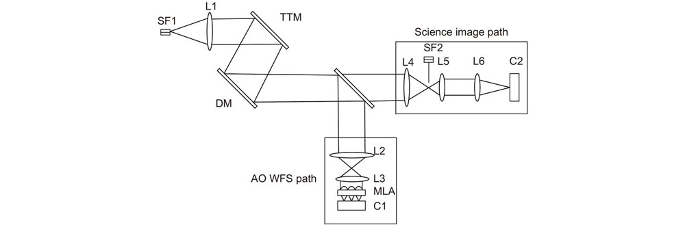
The schematic diagram of the static aberration correction system is shown in Fig. 1. A single-mode fiber (SF1) that can be inserted onto the telescope focal plane is used for the aberration correction and calibration. Then, the light is collimated by lens L1 and reflected by a tip-tilt mirror (TTM), as well as a DM that can be commanded to correct possible wave-front error. A beam-splitter (BS) directs part of the incoming light to the AO WFS path, which consists of lenses L2 and L3, a microlens array (MLA), and a high-speed camera (C1). Another part of incoming light is directed into science image path, the lens L5 is added behind the imaging lens L4 for the aberration correction. Reference light source (SF2) can be inserted into the focal point of L4 to generate a reference PSF. Each time, either the SF1 or SF2 will be used. Please note that SF2 and L5 will be removed after finishing the aberration correction.
Figure 1.The schematic diagram of AO system for correction
In order for getting the best correction result, the alignment procedure is involved before the correction starts: Firstly, open SF1 and the calibrate the center coordinates of AO PSF image sampled by C2 in the science image path. Secondly, block SF1 and insert SF2 into the science image path. Then, adjust the position of SF2 to make the reference PSF imaged at the same position of AO PSF on C2 by using the recorded center coordinates and adjustment frame of SF2. Since SF2 is served as the perfect point source, the reference PSF can be seen as the perfect PSF without aberration. As such, any difference between the AO PSF and reference perfect PSF will be an indication of associated aberrations that need to be corrected.
For correcting those aberrations effectively and rapidly, a well-known iteration optimization algorithm SPGD[12-14] is selected. It applies small random perturbations to all control parameters (i.e. the voltages of DM actuators) simultaneously and then evaluates the gradient variation of a metric functionJ. The control signals are updated in an iterative process using the following rules:
wherek is the iteration number;
is the control voltages applied on DM actuators, n is the number of actuators number of DM;
is the key gain coefficient that is positive for minimizing and negative for maximizing the metric function J. The range of
is (0.1,1).
denotes small random perturbations, which means all elements of
have identical amplitudes and randomness (Bernoulli probability distribution).
is the variation of the SPGD algorithm’s metric function.
To improve the estimation accuracy of
, a two-sided perturbation is used as follow:
The gain coefficient
that is a variable constant can be used to accelerate the convergence:
In our case, the metric function J we designed optimizes the PSF with a perfect reference PSF generated by SF2. It has a perfect Airy disk as the template in the process of optimization. If the Airy disk of PSF generated by SF1 is equal to that of PSF generated by SF2, the static aberration of AO system is corrected. The metric function J is used to evaluate the Airy disk pattern difference between the perfect PSF image generated by SF2 and the AO actual PSF image generated by SF1. For the PSF imaged on C2 with a size of m×n, the metric function J is defined as:
whereII(x, y) is the focal plane intensity in the PSF Airy disk that should have maximum value, Io(x, y) is the intensity in an area around or near the Airy disk that should have minimum value.
(x, y) and
(x, y) are intensities in the same area of perfect PSF generated by SF2. For a perfect point-source image, the energy should gather in the Airy disk of PSF. If the aberration exists, more energy will be pushed into diffraction fringes or areas nearby Airy disk. As such, reference PSF generated by SF2 consists of a bright Airy disk surrounded by minimal diffraction fringes, which means
is an minimal value. For getting best correction performance, the difference between
and
should be optimized to 0. What’s more, taking the logarithm of the difference can amplify the originally small signal and expand the dynamic range of the metric function J, which will expend the gain coefficient
accordingly during the optimization and accelerate the whole optimization process. This metric function J will have a minimum value after the optimization, which corresponds to a minimum difference of Airy disk between PSF generated by SF2 and PSF generated by SF1. In ideal case,
=
. So that, Airy pattern of PSF generated by real AO system can be optimized to be the same to that of perfect PSF generated by reference path, the static aberration is effectively corrected. However, since the existence of measurement noise, real AO system’s PSF cannot be optimized to a perfect one, which means J cannot be optimized to be 0, and a small value can prove that a good performance of optimization is achieved.
The DM voltages can be saved and used as the reference voltages in the AO system, after finishing the correction. Therefore, the perfect PSF can be copied to our actual AO system for normal closed-loop operation by using the reference DM voltages we optimized before.
Laboratory test
The Fig. 2 shows the NCPA correction system in lab. A HENE light source of 632.8 nm is used for this test. The DM provided by ALPAO Corporation has 97 actuators (in 11×11 configuration) and the CCD camera (GEV-B0610M-TC000) purchased from IMPERX has a resolution of 648 pixels×448 pixels. In order to quantitatively measure the wavefront root mean square (RMS) before and after correction, we used the WFS-150-5C wavefront sensor manufactured by Thorlabs. Fig. 3 shows the initial PSF image without aberration correction. Since the AO WFS can’t see the wavefront error induced by optical elements from BS, L4 to C2, initial PSF is somewhat aberrated and has a large initial wavefront error, with a RMS of 109 nm. The Strehl Ratio (SR) can be estimated by the following rule.
Figure 2.The real experimental optical path of AO system for the NCPA measurement and correction
In the following, we will test this optimized correction:
1) Recording the reference perfect PSF. SF1 is blocked and open SF2 and adjust its position for getting the same imaging position with SF1. This allows C2 to record reference PSF only. In addition, this reference PSF can be recorded once in advance and be used repeatedly in future experiment.
2) Aberration correction. Remove the SF2 and open SF1. Then, manually select the center of reference PSF and AO PSF and input the range of area needs optimizing for ensuring that the location of the optimized area is consistent during optimization. Finally, set the proper parameter of SPGD to start the correction, until AO PSF is optimized to be the same as the reference PSF shown in Fig. 4(a)~4(c) show the PSFs corrected with different exposures. The RMS wavefront errors is reduced to 7 nm, which means the SR can be raised to 0.995. The NCPA correction process only takes about 40 min.
Figure 4.Reference PSF and PSFs after correction. (a) Reference PSF image; (b) and (c) are the PSFs corrected with different exposures by using J
In fact, since the system needs time to be stable, an appropriate delay time must be added before sending next round of control voltages. With a commercial desktop (Intel Xeon CPU E5-2680, 2.4GHz; 32GB Rom), 40 min of optimization time is a good value for AO system with a large initial static aberration.
Fig. 5 shows the metric function evolution as a function of iteration steps. For getting extremely high SR, the whole optimization process consists of 4 stages. New SPGD parameters will be set in different stages to accelerate optimization, until metric function has no further reduction by adjusting parameters. Such high SR will dramatically raise the imaging contrast of AO system[15-16]. In comparation, the AO system without wavefront sensor corrected by aberration correction algorithm can’t get such high SR[17]. As the ultra high AO performance presented above, this optimized approach is developed for AO system optimized for high-contrast exoplanet imaging. If AO system used in other application that just need a low SR such as a SR of 0.8[18], the whole optimization time can be significantly reduced, for example, just 8000 steps (nearly 7 min) in stage1 are needed to get an acceptable result.
Figure 5.Metric function evolution as a function of iteration steps
In order to get this best correction result, we also conduct other experiments to prove the real function of our improvement in metric function and optical path design. Here, for demonstrating the advantages of our optimized approach, we will compare them with our optimized approach under the same experiment condition.
First, we conduct our previous focal plane correction approach. Remove the SF2 and L5 from the optical path and open SF1. This allows focal plane camera to directly evaluate the AO system’s PSF. The SPGD algorithm with a metric function Jo is optimized for a minimum energy in a specific area:
Jo is used to find the minimum value of
relative to
. As such, in principle, the corrected PSF should have a maximum enclosed energy in the Airy disk and a minimum energy in the remaining area. Real PSF corrected is shown in Fig. 6. The RMS wavefront errors is reduced to 55 nm. From equation (6), the 55 nm RMS error corresponds to a SR of 0.739 and we can see that there is still much energy remained outside the Airy disk. With a commercial computer, this approach takes 140 min to get an acceptable result.
Second, for optimizing more energy outside into the Airy disk, we took the algorithm ofJo for amplifying the smaller signal outside the Airy disk that may be ignored before and defined it as Jlg, hardware setup and experiment process are the same as our previous focal plane NCPA correction approach.
In this way, since taking the logarithm of Io/II inJlg, the initial value ofJlg during the optimization is rather smaller than that during the optimization by usingJo. As such, we can set a larger gain coefficient
and start the correction, until value of Jlg has no further reduction. PSF corrected byJlg is shown in Fig. 7. Obviously, more energy has been optimized to the Airy disk. Compared with Jo, the RMS can be reduced to 28 nm, which corresponds to a SR of 0.924 and the whole process takes 60 min.
This result proves thatJlg can speed up the process of correction and get better performance. However, it still may deliver a local optimization result, instead of a global one. Therefore, we added a reference PSF in the optimization for avoiding such disadvantage and finally developed this new optimized correction approach.
Experiment results analysis
We listed the above 3 experiments' results in Table 1 for analyzing the real effect of our improvement in this new optimized approach. We can see that taking the algorithm of the value of sumII(x, y) relative to sum Io(x, y) can fully use the weak intensity signal sampled by C2 , more energy in the area outside the Airy disk will be measured. At the same time, it expands dynamic range of metric function, which will reduce the effect of camera's readout noise. From results listed in Table 1, the SR optimized by Jlg is improved 25% than that optimized by Jo, and the correction time is shorten by a factor of 1.3. Based onJlg, a perfect PSF generated by SF2 is added in J to provide a best optimization direction for SPGD. So that, the SR of this optimized focal-plane approach usingJ is improved 7% than that usingJlg and 35% than that using Jo. The correction time is only 67% and 42%, respectively of the time required by usingJlg and Jo.
Compared with the existing traditional correction methods, this optimized approach is also advantageous. The dedicated PD system used for AO NCPA correction only deliver a corrected SR of 0.93 at the 632.8 nm wavelength[19]. Although dedicated interferometers can deliver high precision result, it is severely restricted by the working environment and rather expensive. Here, our optimized approach can deliver a better SR up to 0.995 and have a low cost. The extra hardware required for this optimized approach is only a lens L5. As the correction process presented in section 3, this optimized approach is easy to be deployed in the AO system in real observation or other applications.
Metric function
RMS/nm
SR
Time/min
Jo
55
0.739
140
Jlg
28
0.924
60
J
7
0.995
40
Table 1. Experiment results of different metric functions
In this paper, we propose a focal plane based static aberration correction technique. This technique that is based on focal-plane PSF implements SPGD algorithm to directly command the DM, until Airy pattern of PSF generated by AO science image path and that of perfect reference PSF are exactly same. That means the perfect Airy pattern of reference PSF is copied by our AO system and any potential NCPA has been removed from the system. Because of guidance of perfect reference PSF images during the optimization process, we can get the global optimization result easier and faster. In terms of hardware requirements, this optimized correction system just needs one more lens(L5), compared with the conventional AO system and deliver much better performance: a SR of 0.995 can be achieved from an initial value of 0.305 at the wavelength of 632.8 nm.
Overview: Non-Common Path Aberration (NCPA) is introduced by the physical separation between the science camera path and the wavefront sensor path. At the same time, the static aberration will also be introduced in common path of the AO system. They must be effectively corrected, especially when the AO system is implemented in astronomy or other fields for achieving high-performance imaging. Therefore, we proposed a sample but effective optimized focalplane- based static aberration correction technique. The correction system is similar to the conventional AO system, except that only one lens and a single-mode fiber are temporarily added in the science image path for generating perfect reference point speared function (PSF). Since the existence of static aberration, any difference between the AO PSF and reference perfect PSF will be an indication of associated aberrations that need to be corrected. If the PSF of the AO system can be optimized to be the same as reference perfect PSF, aberration will be effectively corrected. For achieving this optimization result, the reference perfect PSF will be recorded in advance, and then iteration optimization algorithm will optimize the AO system ’s PSF by directly controlling the deformable mirror (DM) with the model of reference PSF, which means copy the reference PSF to the AO system. In addition, we also designed new metrics functions for getting global optimization result rapidly and steadily. The laboratory experiments indicates that this proposed technique can successfully reduce the AO system’s root means square (RMS) from initial value of 109nm to final value of 7 nm and the Strehl Ratio (SR) can be raised from 0.305 to 0.995 accordingly. In conclusion, thte proposed optimized correction technique has the following advantages: 1) Correction system is easy to be deployed and can be flexibly implemented to different types of the AO systems that need extremely high-performance imaging in astronomy or other fields such as biology and medicine. 2) The hardware requirements of correction system are small, which means a low cost. Compared with the conventional AO system, only one more lens is needed temporarily in science image path and it will be removed after finishing correction. 3) The final correction performance is much better than traditional NCPA methods and the method we proposed in 2012, especially when the AO system has a large initial static wavefront error. 4) With the guidance of reference perfect PSF, the whole optimization speed is rapid and the global optimization will be achieved steadily, instead of trapping in local optimization result. This work is demonstrated to be a promising technique, it will be integrated into our coronagraph system for high-contrast imaging of exoplanets in our next study.