
Sławomir Paśko, Marek Sutkowski, Ramunas Bakanas. Use of focus stacking and SfM techniques in the process of registration of a small object hologram[J]. Chinese Optics Letters, 2020, 18(6): 060901
- Chinese Optics Letters
- Vol. 18, Issue 6, 060901 (2020)
![(a) Scheme of the recording set-up. A series of images with limited DoF [examples in (b) and (c)] were used to create (d) a full DoF image with use of FS software. It was repeated for different perspectives (by x and y rotations).](/richHtml/col/2020/18/6/060901/img_001.jpg)
Fig. 1. (a) Scheme of the recording set-up. A series of images with limited DoF [examples in (b) and (c)] were used to create (d) a full DoF image with use of FS software. It was repeated for different perspectives (by
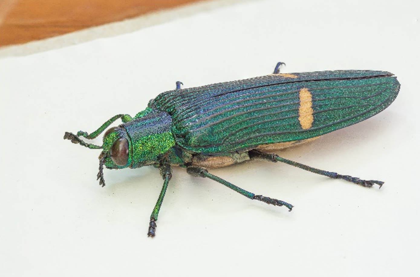
Fig. 2. Sample final input image (with increased DoF) used for 3D data reconstruction by SfM.
Fig. 3. Virtual set-up for generation of multiple views preparation for digital holographic printer. The image is shown in the
Fig. 4. Optical printer scheme for one color. Three identical schemes are coupled together for the three primary colors, or red–green–blue (RGB) laser beams are combined into one ‘white light’ beam and put through one apochromatic objective.
Fig. 5. Hogel formation for a single-parallax digital holographic print: 1, the SLM; 2, the principal focus (behind Hogel); 3, the FOV of individual SLM pixels from Hogel; 4, the Hogel recording position just downstream of the focus; RB, the reference beam.
Fig. 6. Final result of reconstruction of point clouds of the measured microscopic object—an insect.
Fig. 7. Sample views of printed single-parallax digital hologram made of cloud of points. Final dimensions are
Fig. 8. Flowchart of activities. ImRec, registration of series of input images; FocStack, focus stacking process; SfM, shape reconstruction (75 min); ImGen, calculation needed by the Geola Digital Holoprinter (180 min); HolRec, printing of the final hologram.

Set citation alerts for the article
Please enter your email address
© Copyright 2018-2021 | Chinese Laser Press. All Rights Reserved 沪ICP备15018463号-20