
Sławomir Paśko, Marek Sutkowski, Ramunas Bakanas. Use of focus stacking and SfM techniques in the process of registration of a small object hologram[J]. Chinese Optics Letters, 2020, 18(6): 060901
- Chinese Optics Letters
- Vol. 18, Issue 6, 060901 (2020)
Abstract
As per holographic printing system requirements, the pre-processing stage has to generate a series of two-dimensional (2D) images of the object(s) to be imaged on the holographic print, and said images shall fulfill certain geometrical assumptions. There is no limitation for using real or virtual objects or even a combination of these. One possible application of the mentioned system is digital documentation and archiving of objects of cultural heritage. A generation of three-dimensional (3D) digital models of such objects is very popular nowadays and applied widely in practice. Obtained results are usually used as a presentation of a virtual model of the real objects on the computer screen, as passive or interactive objects. There is no way to display or visualize such models without optical aids such as virtual reality goggles. The only way to produce 3D images visible to the naked eye is holographic prints. The standard way of using 3D scanning data for the holographic printing process includes conversion of acquired data (cloud of points) into triangle mesh, texturing, virtual light operation, and finally generating input data for the holoprinter. Disadvantages of such a way are highly noticeable when the objects have a complex shape, which in effect causes errors and/or discontinuities in a resulting model. To eliminate these faults in the final virtual 3D model, a time-consuming manual operation performed by a highly experienced person is needed. Elimination of this stage of manual operation simplifies a pre-processing procedure, but the whole data acquisition process requires a proper scanning system anyway. In the experiment, we used an automated Optographx (OGX) scanner applied by Wilanów Historic Museum in Warsaw (Polska). A cloud of points is generated by this scanner.
Shape measurements of microscopic objects can be done by active or passive systems. Widely known active systems use in most cases structures or patterns projected onto an object under measurements, and then a shape reproduction is calculated. The disadvantage of these methods is the limitation of applicability for diffused objects only. Any type of reflective surfaces can be measured only after application of the scattering layer (which is hard to apply and/or hard to remove). Passive systems do not project any patterns on measured objects, and thus the camera cannot be blinded by light reflected from any part of the object. Consequently, for some object types (i.e., reflective or partially reflective ones), the passive systems are better. On the other hand, many of active and passive methods of shape measurements are completely useless for objects variable in time.
Among popular passive methods used for microscopic objects, confocal microscopy can be noticed, for instance[
Sign up for Chinese Optics Letters TOC. Get the latest issue of Chinese Optics Letters delivered right to you!Sign up now
The shape measurement system presented in this Letter can reconstruct 3D shapes of the microscopic object from multiple camera views. The SfM theorem assumes unknown or partially unknown parameters of the camera, which additionally may be unstable in time. With the use of a set of
Images taken with the use of traditional optical microscopes are characterized by an insufficient (in most cases) depth of field (DoF). However, the optical microscopes nowadays are present practically everywhere; the availability and ease of use is excellent, but the insufficient DoF is a huge disadvantage of it. One of the possible solutions for this problem can be the use of the FS technique, which allows us to increase the depth of focus by use of multiple images. The FS method applied for the mentioned purpose only is relatively simple in use and is effectively utilized by many classic microscopy users [i.e., the extended DoF (EDF) imaging method][
However, the SfM method of 3D model creation is relatively tolerant of image imperfections (for example, caused by aberrations); it fails when the algorithm does not recognize sufficient similarities (i.e., matching points) in a series of source images of the same object area taken from different perspectives. This will occur even when input images are blurry or have insufficient depth of focus (can also be interpreted as a blur). In this Letter, we propose to link these two techniques for microscopy like it was done for other purposes by, for example, Clini et al.[
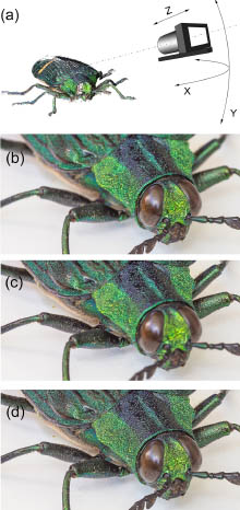
In the case of this work, we decided to use a biological specimen as an object—a prepared imago of the Asian beetle of Catoxantha opulenta family. It was originally glued to a small white base made of paper.
Images were registered with use of a high resolution color digital camera with a total number of effective pixels of 24 million, equipped with a specialized optical set-up, allowing the required magnification of the image to be equal to 1 and larger (Sony alpha 6000 with MD Macro Rokkor
The prepared images used later in the FS process were taken as a consecutive series varying by points of view (perspective). The origin position of the camera was a result of changing angles of the
![]()
Figure 1.(a) Scheme of the recording set-up. A series of images with limited DoF [examples in (b) and (c)] were used to create (d) a full DoF image with use of FS software. It was repeated for different perspectives (by
The process of registration of input images consists of two consecutive stages: registration of a series of images with a fixed direction of the optical axis, the optical axis aligned with the center of the specimen, and variable object distance for increasing DoF; repeating the series as above with variable camera positions (with variable angles between the optical axis and base stage plane and variable angles of stage rotation around its own axis). All images were recorded as RAW-type files and were processed with use of Photoshop software FS method.
The SfM method implemented in VisualSfM software[
Each resulting image taken after the FS process (with large DoF) was then used as an input image for the SfM method. The SfM algorithm needs to use more than a few images (practically, a minimum of ten) from different viewpoints. Additionally, input images should give the possibility of finding similarities (matches) between neighboring images; thus, they have to overlap, and each of the selected viewpoints cannot differ in distance too much. In the case when the specimen rotates, it means that each rotation should possibly be small—in the experiment, it was maintained to not to exceed approx. 10 deg between consecutive camera positions. A total number of 10 final input images (with increased DoF) showing specimens from varying camera viewpoints was taken into the SfM for 3D data reconstruction. Samples of these images are shown in Fig.
![]()
Figure 2.Sample final input image (with increased DoF) used for 3D data reconstruction by SfM.
![]()
Figure 3.Virtual set-up for generation of multiple views preparation for digital holographic printer. The image is shown in the
![]()
Figure 4.Optical printer scheme for one color. Three identical schemes are coupled together for the three primary colors, or red–green–blue (RGB) laser beams are combined into one ‘white light’ beam and put through one apochromatic objective.
![]()
Figure 5.Hogel formation for a single-parallax digital holographic print: 1, the SLM; 2, the principal focus (behind Hogel); 3, the FOV of individual SLM pixels from Hogel; 4, the Hogel recording position just downstream of the focus; RB, the reference beam.
Final results of a shape reconstruction—a point cloud view—are shown in Fig.
![]()
Figure 6.Final result of reconstruction of point clouds of the measured microscopic object—an insect.
In Fig.
![]()
Figure 7.Sample views of printed single-parallax digital hologram made of cloud of points. Final dimensions are
The flowchart of the process is given in Fig.
![]()
Figure 8.Flowchart of activities. ImRec, registration of series of input images; FocStack, focus stacking process; SfM, shape reconstruction (75 min); ImGen, calculation needed by the Geola Digital Holoprinter (180 min); HolRec, printing of the final hologram.
With use of the data collected and processed and a digital holographic printer described above, a final hologram of the virtual object represented as a cloud of points was printed. The size of the hologram is
Proposed fusion of two well-known methods allows us to correctly reconstruct a 3D shape of the small microscopic objects (i.e., small insects). This method can be applied where specialized hardware is not present. All of the experimental work can be performed with the use of very basic equipment: a typical microscope with a camera mount, high resolution digital camera, and simple diffused light source. The simplification on the hardware side is paid by more manual work that is necessary to capture hundreds of images (a dozen or so for FS calculation multiplied by number of different camera viewpoints needed by SfM). The registration of the series of images at different object distances can be automatized, of course, but if so it leads to evidently expanded hardware equipment.
However, the proposed method needs a lot of calculations to be performed in post processing; the satisfactory results can be done without use of specialized software. In this Letter for SfM, reconstruction freeware and open access software were used.
Objects that are relatively complicated (as an insect shown in this experiment) need as many as possible different views for reconstruction. The number of 10 views is absolutely the minimum, and, in future work, it should be greater. In the experimental example shown in this Letter, the significant increase of the number of views (with large DoF) will give better shape reconstruction (i.e., more points in the cloud, less “blank” areas). It is clear that the number of views necessary for good quality shape reconstruction strongly depends on the actual object selection and should be determined individually for actual conditions and used equipment.
As it was proved, the data collected within the presented experiment can be used for further processing in virtual space and/or 3D computer graphics. It allows us to acquire shapes of real objects of a microscopic scale without use of sophisticated hardware.
This method of shape reconstruction does not quite need any special conditions regarding the specimen used, and thus it can be applied in many applications and many types of objects. The only limitation is to have objects stable in time (possibly lifeless or stable in time).
Digital holographic printers developed by Geola Digital for hologram production need parallax-related image sequences. Instead of the well-known method of data recording from real objects by use of HoloCams, said holographic printers also accept images obtained from virtual representations of the object. In this Letter, a range of possible representation of virtual objects is widened by a cloud of points. In comparison to the “standard” method using a complex textured shape of the triangular net, the presented method eliminates one step of data processing. It can be applied in the systems where the conversion from cloud of points to triangular mesh is impossible, complicated, or excessively time consuming.
References
[1] J. B. Pawley. Handbook of Biological Confocal Microscopy,(2006).
[2] A. W. Fitzgibbon, A. Zisserman. Lect. Notes Comput. Sci., 1406, 311(1998).
[3] S. Muhamad, M. Hebert. IEEE Conference on Computer Vision and Pattern Recognition, 2, 430(2000).
[4] O. Faugeras, Q. T. Luong, T. Papadopoulo. The Geometry of Multiple Images(2001).
[5] L. Liu, I. Stamos, G. Yu, G. Wolberg, S. Zokai. IEEE Conference on Computer Vision and Pattern Recognition, 2, 2293(2006).
[6] F. Aguet, D. Van De Ville, M. Unser. IEEE Trans. Image Process., 17, 1144(2008).
[7] A. G. Valdecasas, D. Marshall, J. M. Becerra, J. J. Terrero. Micron, 32, 559(2001).
[8] S. Paśko, M. Sutkowski. Devices Methods Meas., 7, 305(2016).
[9] B. Forster, D. Van De Ville, J. Berent, D. Sage, M. Unser. Microsc. Res. Tech., 65, 33(2004).
[10] P. Clini, N. Frapiccini, M. Mengoni, R. Nespeca, L. Ruggeri. International Archives of the Photogrammetry, Remote Sensing and Spatial Information Sciences, XLI-B5, 229(2016).
[11] G. Kontogianni, R. Chliverou, A. Koutsoudis, G. Pavlidis, A. Georgopoulos. International Archives of the Photogrammetry, Remote Sensing and Spatial Information Sciences, XLII-2/W3, 385(2017).
[12] C. Wu. VisualSFM: a visual structure from motion system,(2017).
[13] C. Wu, S. Agarwal, B. Curless, S. M. Seitz. IEEE Conference on Computer Vision and Pattern Recognition, 3057(2011).
[14] Y. Furukawa, J. Ponce. IEEE Trans. Pattern Anal. Mach. Intell., 32, 1362(2010).
[15] Geola uab. full color holographic photosensitive material(2019).
[16] Geola PBU-Amidol bleach photochemistry for holography(2019).

Set citation alerts for the article
Please enter your email address
© Copyright 2018-2021 | Chinese Laser Press. All Rights Reserved 沪ICP备15018463号-20