1State Key Laboratory of Precision Measurement Technology and Instruments, Department of Precision Instrument, Tsinghua University, Beijing 100084, China
2School of Life Sciences, Tsinghua University, Beijing 100084, China
3Senior Department of Orthopedics, The Fourth Medical Center of Chinese PLA General Hospital, Beijing 100853, China
4IDG/McGovern Institute for Brain Research, Tsinghua University, Beijing 100084, China
【AIGC One Sentence Reading】:We developed a method for simultaneous dual-region two-photon imaging, covering a large span of 9 mm in vivo. This technique, utilizing a custom micro-mirror and spatio-temporal multiplexing, advances the study of correlated biodynamical processes across distant regions, vital for systematic biology research.
【AIGC Short Abstract】:We developed a custom micro-mirror unit to extend the simultaneous imaging range, enabling dual-region two-photon imaging across a 9 mm span. This innovation overcomes the field-of-view limitations of traditional microscopes, facilitating the study of correlated biodynamical processes across large distances. Our system's performance was validated through in vivo imaging of neural and vascular activities in mice, advancing research in system biology and neuroscience.
Note: This section is automatically generated by AI . The website and platform operators shall not be liable for any commercial or legal consequences arising from your use of AI generated content on this website. Please be aware of this.
Abstract
Biodynamical processes, especially in system biology, that occur far apart in space may be highly correlated. To study such biodynamics, simultaneous imaging over a large span at high spatio-temporal resolutions is highly desired. For example, large-scale recording of neural network activities over various brain regions is indispensable in neuroscience. However, limited by the field-of-view (FoV) of conventional microscopes, simultaneous recording of laterally distant regions at high spatio-temporal resolutions is highly challenging. Here, we propose to extend the distance of simultaneous recording regions with a custom micro-mirror unit, taking advantage of the long working distance of the objective and spatio-temporal multiplexing. We demonstrate simultaneous dual-region two-photon imaging, spanning as large as 9 mm, which is 4 times larger than the nominal FoV of the objective. We verify the system performance in in vivo imaging of neural activities and vascular dilations, simultaneously, at two regions in mouse brains as well as in spinal cords, respectively. The adoption of our proposed scheme will promote the study of systematic biology, such as system neuroscience and system immunology.
1. INTRODUCTION
In life science, especially neuroscience, the recording of biological dynamic activities in vivo has become increasingly indispensable [1–3]. The necessity of using larger model animals in biomedical research, such as ferrets [4] and monkeys [5], further raises the requirements of large-scale recording of biodynamics in vivo. Due to the advantages in low invasion, low toxicity, and high spatial resolutions, optical microscopes are widely used in in vivo recording, among which, multiphoton fluorescence microscopes have the capability of large penetration depths, benefiting the imaging of biological activities in vivo [1,2,5,6].
However, due to the limited field-of-view (FoV) of commercial objectives of high NA, large-scale imaging is still challenging. To simultaneously record neural activities at different brain regions with long lateral separations, multiple mesoscale two-photon microscopes in vivo have been proposed [7–10]. On one hand, several custom mesolenses have been designed to support FoV of at sub-micron lateral resolutions [8–10]. On the other hand, dual-axis two photon microscopy with more degrees of freedom has also been developed for multi-region imaging, from nearby (3.5 mm) to distal [11]. However, both of them are complex custom systems and of high cost, which undoubtly affects their wide adoption in biomedical study.
Alternatively, with an objective of long working distance and high numerical aperture, the deflection of excitation beam after the objective can be used to extend the FoV. By placing micro mirrors after the objective lens, large imaging FoV, i.e., up to more than 6 mm in diameter, has been achieved for long-distance neural activity recording [12]. However, to switch among different imaging regions-of-interest (ROIs), the micro mirrors after the objective lens need to be rotated rapidly, in which mechanical inertia limits the maximal imaging speed.
Sign up for Photonics Research TOC. Get the latest issue of Photonics Research delivered right to you!Sign up now
Here, to achieve simultaneous dual-region imaging, we take advantage of the long working distance of the objective with custom post-objective optics along with spatio-temporal multiplexing. We use a commercial objective of 8 mm working distance and a custom micro-mirror unit (MMU) to align the excitation beams to two ROIs. The excitation beams with different time delays are reflected by the MMU and focused to different transverse ROIs, while the excited fluorescence signals are detected and temporally demultiplexed. We achieve simultaneous imaging of two ROIs with a lateral interval of as large as 9 mm, which is 4 times larger than the nominal FoV (1.8 mm) of the objective. We verify the system performance by simultaneous dual-region imaging on pathological sections of human squamous epithelium and brain slices of Thy1-YFP mice. Then, we demonstrate the simultaneous dual-region recording of neural activity and cerebral vascular dynamics in mouse brain and spinal cord, respectively, in vivo.
2. METHODS
A. Microscope System
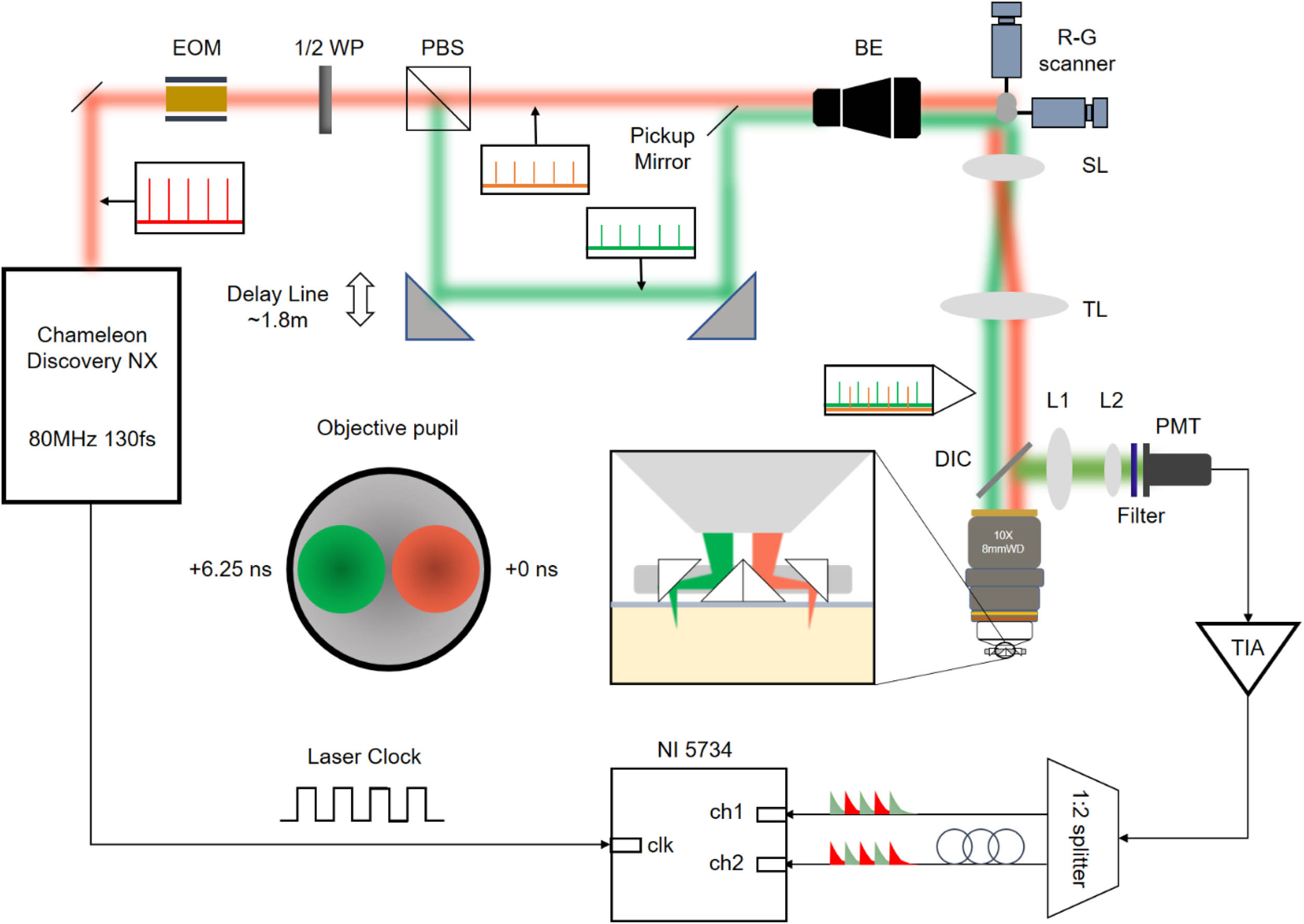
The system diagram is shown in Fig. 1. We use an 80 MHz femtosecond laser (Chameleon Discovery, Coherent) as the excitation source and a Pockels cell (Pockels cell, 350-80-LA; Controller, 302RM, Conoptics, Inc.) to adjust the laser power injected on the samples. The imaging laser wavelength is fixed at 920 nm. We employ spatiotemporal multiplexing of two beams for dual-region two-photon imaging simultaneously. A halfwave plate (AHWP05M-980, Thorlabs) and a polarization beam splitter (CCM5-PBS202/M, Thorlabs) are placed after Pockels cell to adjust the excitation powers of two excitation beams, in which one undergoes a time delay of 6.25 ns relative to the other [7,9,10,13–18]. Then the two beams are combined by a pickup mirror (PFD10-03-P01, Thorlabs). Even though these two beams have the same propagation direction, they do not overlap in space. Following that, the two beams are expanded by an adjustable beam expander (BE02-05-B, Thorlabs) to match the size of the subsequent scanning galvanometer pair (8315 K & CRS 8 kHz, Cambridge Technology) and relayed to the back focal plane of an objective of 8 mm working distance and 1.8 mm FoV (XLPLN10XSVMP, NA 0.6, , Olympus) by a scan lens (SL50-2P2, Thorlabs) and tube lens (TTL200MP2, Thorlabs) pair. An MMU (Taizhou Jingda Optic Electric) is placed after the objective to reflect the excitation beam with different time delays to different ROIs [12,19–21]. Fluorescence signals are epi-collected by the objective and reflected by a long pass dichroic mirror (DMLP805R, Thorlabs), followed by being converged by a lens pair (#49-284, Edmund; KPA034-C, Newport) and detected by a photomultiplier tube (PMT) (H10770PA-40, Hamamatsu) after being filtered by a short pass dichroic mirror (ZT775sp-2p-UF1, Chroma) and a green filter (FF03-525/50-30-D, Sermock).
Figure 1.System scheme of simultaneous dual-region imaging microscopy. Two excitation beams with a relative time delay of 6.25 ns are introduced by an optical delay line of . These two beams are relayed to different positions of objective back pupil and further reflected to two ROIs by the MMU. The excited fluorescence signals are detected by a PMT and amplified, followed by temporal demultiplexing with synchronization signals from the clock of the laser. L, lens; EOM, electro-optic modulator; 1/2 WP, halfwave plate; PBS, polarization beam splitter; BE, beam expander; SL, scan lens; TL, tube lens; DIC, dichroic mirror; PMT, photomultiplier tube; TIA, transimpedance amplifier.
Then, temporal demultiplexing should be performed to split the signals from two regions. The PMT signals corresponding to two ROIs are first amplified by a high-speed current amplifier (DHPCA-100, Femto) and then split into two channels by a power splitter (ZAPD-30-S+, Mini-Circuits) [18]. Then two channels are connected to the high-speed data acquisition card (NI-5734, NI) through two cables of different lengths ( difference) to achieve a 6.25 ns time delay relative to each other. The cable length of the laser sampling clock is also adjusted to make sure that the peak of the fluorescence signal is recorded.
The system is controlled by ScanImage 2018 (scanimage, Vidiro). Taking advantage of spatiotemporal multiplexing, optical switching between the two regions occurs at a nanosecond-level (6.25 ns) speed. This switching speed significantly surpasses the mechanical scanning speed of the galvo scanner. Consequently, with a single complete two-dimensional scan, image acquisitions for both fields are realized. During imaging, the scanning galvanometer pair provides the same optical scanning degree to both excitation beams. Thus, as the PMT detects fluorescence signals from both ROIs, without employing spatiotemporal multiplexing and temporal demultiplexing, fluorescence signals from both fields would overlap. Temporal demultiplexing allows us to differentiate the fluorescence images from the two regions based on distinct arrival times of the fluorescence signal at the detector. Limited by the fluorescence lifetime and the bandwidth of the current amplifier, there will be some residual signal crosstalk between two channels. However, the residual crosstalk is linear and relatively stable. Thus, we perform linear demixing to eliminate this crosstalk [15].
B. Micro Mirror Unit
Drawings and a photo of the MMU are shown in Figs. 2(a) and 2(b). The design of the MMU determines the interval of two simultaneous imaging ROIs and the efficiencies of two-photon excitation and fluorescence collection. The distance between imaging ROIs depends on the interval between the pair of mirrors. Thus, the interval between two ROIs is where 0.5 mm is the unpolished interval between middle micro mirrors [Fig. 2(a)] to satisfy the requirements of mechanical and optical manufacturing.
Figure 2.Drawings and photos of the MMU, and system resolution calibration. (a) Top and side views of the MMU. (b) Photo of MMU with (left) and (right), corresponding to 2.5 mm working distance, 7 mm center interval of the effective FoV and 1.5 mm working distance, 9 mm center interval of the effective FoV, respectively. (c) Drawing of the 3D printing objective sleeve. (d) Photo of the 3D printing objective sleeve. (e) XY and XZ sections of PSF of region 1. Region 1 is the FoV corresponding to the excitation beam of + 0 ns time delay. Scale bar: 5 μm. (f) XY and XZ sections of PSF of region 2. Region 2 is the FoV corresponding to the excitation beam of + 6.25 ns time delay. (g)–(i) x, y, z intensity profiles (dot) and their Gaussian fitting curves (curve) of the system PSF of region 1. (j)–(l) x, y, z intensity profiles (dot) and their Gaussian fitting curves (curve) of the system PSF of region 2.
However, the system vignetting would affect actual interval of the ROIs. In the dual-region two-photon imaging system, vignetting mainly happens when the edges of the micro-mirror block some of the excitation beam, especially at larger scanning angles. Considering how the excitation beam focuses, vignetting mostly occurs at the first mirror after the excitation beam enters the MMU. Thus, vignetting stays consistent for MMUs of different . As the distance between the objective lens and the MMU decreases, the vignetting in the system becomes more pronounced. Through practical measurement, the center interval of the effective FoVs is
In post-objective optics, a part of the long working distance is utilized to ensure large intervals of the ROIs. Considering that the working distance of the objective is 8 mm and the side length of the mirror of the isosceles right triangle shape is 2.5 mm, the maximal effective working distance is related to the interval between the mirrors:
As examples, we design two sets of MMUs with and , respectively. With , the actual working distance is 2.5 mm, and the center interval of the effective FoVs is 7 mm. And with , the actual working distance is 1.5 mm, and the center interval of the effective FoVs is 9 mm. To improve the efficiency of signal excitation and collection, the mirror of the MMU is designed in a rectangle shape, and the side with no mechanical restrictions [12] is extended to 4 mm.
To facilitate the connection of the MMU and the objective lens, we fabricate an objective lens sleeve by 3D printing. Subsequently, the MMU is affixed to the end of the objective lens sleeve. The modified sleeve, housing the MMU, is then mounted onto the objective lens [Figs. 2(c) and 2(d)]. Thus, the objective lens sleeve does not block the imaging path. The MMU is typically positioned closely to the objective lens to maintain a large working distance with the biological sample. By carefully rotating the sleeve, the excitation beams with different time delays could be directed through the corresponding mirrors, thereby yielding dual-region two photon imaging. We then use the 3D motorized stage (MT3-Z8, Thorlabs) to move the biological samples for imaging at different locations.
To characterize the spatial resolution of the system, we measure the point spread function of our system by imaging 0.51 μm green fluorescent polymer microspheres (Fluoro-Max, diameter 0.51 μm, Thermo Fisher Scientific) buried in 2% agarose gel. Cross sections of green fluorescent polymer microspheres are illustrated in Figs. 2(e) and 2(f). The X, Y, and Z resolutions in full-width-at-half-maximum of two ROIs are calibrated as μ, μ, μ and μ, μ, μ, respectively () [Figs. 2(g)–2(l)]. The side length difference of the mirror will lead to difference in the point spread function in X and Y directions, as shown in Figs. 2(g) and 2(h) and Figs. 2(j) and 2(k). The measured results indicate that the numerical aperture of the excitation beams in both regions is (lateral 1.16 μm; axial 16.9 μm) [22].
C. Surgery
All experimental procedures related to animals are carried out in accordance with protocols approved by the Institutional Animal Care and Use Committee, Tsinghua University.
1. Brain Cortex Surgery
We perform craniotomy on Ai162(TIT2L-GC6s-ICL-tTA2)-D mice (JAX: 031562) for calcium imaging. Craniotomy surgery is performed by removing the skull within range to 3 mm A/P and 0 to 5 mm M/L. A circular glass coverslip is carefully positioned and sealed with cyanoacrylate adhesive, and a stainless-steel head-post is securely attached to the skull using dental cement. Anesthesia is initiated with 5% isoflurane before surgery and maintained at 1.5% isoflurane throughout the surgical procedure.
Prior to cortex surgeries, mice are administered dexamethasone (1 mg/kg) and meloxicam (8 mg/kg) subcutaneously. After the surgery, meloxicam (4 mg/kg per day) is given subcutaneously for 3 consecutive days. Mice are allowed to recover for 4 weeks before calcium imaging experiments. During imaging, the mice are kept in darkness and not disturbed by the external environment.
For acute imaging of vascular dilation in mouse brains in vivo, FITC (70,000 MW, Sigma Aldrich) is injected into the infraorbital vessels (2% mass-to-volume ratio in saline, 200 mg/ kg) for staining the blood plasma.
2. Spinal Cord Surgery
The dorsal surface above the thoracic spinal region of the mouse is shaved and washed with iodophor twice to prevent infection. Then we perform laminectomy [23–25] at the T10-T11 level of mouse spinal cords. Anesthesia is initiated with 5% isoflurane before surgery and maintained at 1.5% isoflurane throughout the surgical procedure. Metal bars are employed to clamp three vertebrates on both sides of the imaging area to immobilize the cord. The FITC fluorescent dye is injected into the infraorbital vessels (2% mass-to-volume ratio in saline, 200 mg/kg) for staining the blood plasma.
3. Results
A. Simultaneous Dual-Region Imaging of Mouse Brain Slices
To demonstrate the imaging performance of our system, we first perform simultaneous dual-region imaging of mouse brain slices. We use coronal sections of 50 μm thickness from Thy1-YFP (H line) mouse brains, where neurons are sparsely labeled with yellow fluorescence protein in the cerebral cortex and hippocampus. The schematic diagram of the MMU during imaging is shown in Fig. 3(a). We use a custom wide field fluorescence microscope to capture the whole slide image of brain slices, as shown in Fig. 3(b).
Figure 3.Simultaneous dual-region imaging of a Thy1-YFP mouse brain section and an H&E stained pathological section. (a) 3D model of MMU. (b) Whole slice imaging of the coronal section from Thy1-YFP mouse brain. The interval between two simultaneous imaging ROIs is 7 mm. Scale bar: 1 mm. (c), (d) Two-photon fluorescence imaging results corresponding to the regions in cyan box and pink box, respectively, in (b). Scale bar: 100 μm. (e) Whole slide bright field image of the pathological slice (thickness: 3 μm). The interval between two simultaneous imaging ROIs is 9 mm. Scale bar: 3 mm. (f), (g) Zoom-in views of the regions in the cyan box and red box, respectively, in (e). Scale bar: 100 μm. (h), (i) Two-photon fluorescence imaging results corresponding to the regions in the cyan box and red box, respectively, in (e). Scale bar: 100 μm.
In Figs. 3(c) and 3(d), we demonstrate simultaneous dual-region two-photon imaging of a mouse brain slice at the positions indicated by the cyan and pink boxes, respectively, in Fig. 3(b). In this experiment, we place a (see Section 2) MMU after the objective to achieve an actual ROI interval of 7 mm. As shown in Figs. 3(c) and 3(d), the neuronal morphologies are clear, which indicates that our system would be useful for simultaneous dual-region imaging of neural activity in vivo.
B. Simultaneous Dual-Region Imaging of H&E Stained Pathological Sections
To further demonstrate the potentials of our method, we perform simultaneous dual-region imaging of H&E stained human squamous epithelium pathological samples, with a larger interval between ROIs [Fig. 3(e)]. Here we use an MMU with , which leads to a 9 mm interval between two simultaneous imaging regions.
The zoom-in views of the histological section image in Fig. 3(e) are recorded in bright field mode and our two-photon autofluorescence imaging mode, as shown in Figs. 3(f) and 3(g) and Figs. 3(h) and 3(i), corresponding to the regions in the cyan and red boxes, respectively. The bright field images are well-matched with the images captured by our system, which confirms the ability of our system in cross-region imaging and image demodulation.
C. Simultaneous Dual-Region Imaging of Neuronal Activity in Mouse Cortex in vivo
We then perform in vivo imaging experiments to further validate our method in more complicated biological samples. To demonstrate simultaneous calcium imaging in two brain areas, we perform craniotomy on Ai162 mice, with one side of the craniotomy window reaching 7.5 mm [Fig. 4(a)].
Figure 4.Simultaneous dual-region imaging of neuronal activities in mouse cortex in vivo. (a) Wide field image of the mouse brain cortex under the craniotomy window. B: location of bregma. L: location of lambda. Scale bar: 1 mm. (b) Neuronal activities extracted from the simultaneous dual-region recording in . Colors of boxes denote different regions in (a). Cyan: Region 1. Pink: Region 2. (c) Calcium traces of selected neurons from Region 1. (d) Calcium traces of selected neurons from Region 2. (e) Neurons in two regions and their correlations based on calcium activities. Scale bar: 100 μm. Red lines between two regions link pairs of neurons of high correlation coefficients (CCs) from different regions (). Grey lines link pairs of neurons of correlation coefficients within one region (left, ; right, ). (f) Correlation coefficient matrix from all traces in (b) of Region 1. (g) Correlation coefficient matrix from all traces in (b) of Region 2. (h) Distribution of the correlation coefficient in Region 1, Region 2, and cross regions.
In this experiment, we use the MMU of . Thus, the center interval of dual regions for simultaneous imaging is 7 mm, much larger than the FoV of normal two-photon microscopes. We then use the dual-region two photon microscope to simultaneously monitor calcium dynamics of layer 2/3 neurons. The coordinates for the two imaging positions are 2.7 mm A/P, 2.0 mm M/L, and , 3.0 mm M/L, respectively. The mice are awake and head-restrained under the objective during the imaging. The frame rate of dual-region imaging in this experiment is 60 Hz. We then extract neuronal activity from both regions using suite2p (Python) [26]. We apply median filtering to the original activity traces of neurons and subtract fluorescence fluctuations in the surrounding neuropil of each cell with a coefficient of 0.7. is calculated for each neuron, and is calculated as mean intensity of the 10% frames with the lowest fluorescence intensity. The calcium activities in of both regions are shown in Fig. 4(b). Neural activities of typical neurons from both regions are demonstrated in Figs. 4(c) and 4(d). We further perform correlation analysis to study both the similarity of neural activities within the two imaging regions and the functional correlation between two distant imaging ROIs [Fig. 4(e)]. We identify 34 and 33 active neurons in Region 1 and Region 2, respectively. The correlation of neuronal activity within two imaging ROIs, along with the distribution of correlation coefficients and the inter-region correlation distribution, is illustrated in Figs. 4(f)–4(h).
D. Simultaneous Dual-Region Imaging of Neuronal Activity in Mouse Cortex in vivo
We also perform dual-region dynamic imaging of vascular dilation in mouse brains in vivo. The dilation of the vessel usually reflects the change of oxygen demand of local tissues and neurovascular coupling. Figure 5(a) shows the photo of the acute craniotomy window on the mouse brain and the imaging ROIs.
Figure 5.Simultaneous dual-region imaging of FITC-labeled vessels in mouse brain and in mouse spinal cord in vivo. (a) Photo of the craniotomy window on the mouse brain. (b), (c) Two-photon fluorescence imaging results corresponding to the regions in cyan box and pink box in (a), respectively. Scale bar: 100 μm. (d) Simultaneous recording of vascular dilation in two different regions of mouse brain. Pink and cyan: diameter changes of the indicated vessel in (b) and (c), respectively. (e) Photo of the craniotomy window on the mouse spinal cord. (f), (g) Two-photon fluorescence imaging results corresponding to the regions in the cyan box and pink box in (e), respectively. Scale bar: 100 μm. (h) Zoom-in views of the area labeled in the dashed box in (f) at different time points. Scale bar: 30 μm.
We then use the dual-region two photon microscope to monitor vascular dynamics in mouse brains in vivo. The mice are awake and head-fixed during the imaging session. The frame rate of dual-region imaging, 7 mm apart, in this experiment is 30 Hz. The diameters of blood vessels are measured in Fiji by plugins “diameter,” as shown in Figs. 5(b) and 5(c). From Fig. 5(d), we can see the changes of the vascular diameter over time. Different from the dynamical observations of local brain vessels in Ref. [27], the dilations of two vessels in distant dual-regions are not well synchronized. The capability of long-distance dynamic imaging of vascular dilation provides a novel method of neurovascular coupling study in vivo.
E. Simultaneous Dual-Region Imaging of Vascular Dilation in Mouse Spinal Cord in vivo
The spinal cord relays sensory information from the body to the brain and sends motor output back to the body’s muscles and glands. Deeper understanding of the spinal cord and its functions is essential for developing new treatments for neurological disorders. Here we demonstrate simultaneous dual-region imaging of vascular dilation on mouse spinal cord in vivo [Figs. 5(e)–5(g)]. The blood vessels in the spinal cord are imaged with MMU of , corresponding to a 7 mm interval between ROIs. The photo of the acute craniotomy window on the mouse spinal cord and the imaging ROIs are shown in Fig. 5(e). During imaging, anesthesia is maintained at 1.5% isoflurane to reduce mouse movements. The frame rate of dual-region imaging in this experiment is 30 Hz. Different from the observations above, no apparent vascular dilation is recorded. Instead, we observe the movements of blood cells in capillaries [Fig. 5(h)], demonstrating the potential of our system to study blood supply in mouse spinal cords.
4. DISCUSSION AND CONCLUSION
We propose a simultaneous dual-region, two-photon imaging system based on custom MMUs and spatio-temporal multiplexing. We split the imaging beam and introduce a time delay to one relative to the other. These two beams are relayed to different positions of the objective back pupil and go through different paths in MMUs. The excited fluorescence signals are collected by MMUs and the objective, and are detected by a PMT for temporal demultiplexing with synchronization signals from the laser clock.
We show simultaneous dual-region imaging in vitro and in vivo, including human squamous epithelium pathological sections and Thy1-YFP mouse brain slices, as well as neural network activities and vascular dilations in mice in vivo. These results suggest that our system is competent in recording biodynamics spanning large intervals at high spatiotemporal resolutions.
Instead of expanding FoVs with custom mesolenses as in two-photon mesoscopes [7–10], our system realizes simultaneous imaging of two regions spanning over large intervals by placing post-objective MMUs. Compared to other reports, the MMU used in our system is of low costs (). Therefore, our approach provides a cost-effective and easily adaptable method for long-distance dual-region imaging.
Even though the excitation and collection NAs of the imaging system are reduced in the current design, resulting from the underfilling of the objective pupil by the excitation beam and the partial block of collection path by the MMU, the experiment results confirm that our system can still achieve single neuron resolutions while maintaining the optical sectioning capability. To further enhance the collection efficiency of our microscope, a potential approach is positioning customized silicon photomultipliers (SiPMs) beneath the MMU [28].
For the MMU, in order to reduce energy loss and improve photon utilization efficiency, its size should be as large as possible. Besides, in our experiment, the micro-mirror spacing is set to 3 mm or 4 mm, corresponding to the center interval 7 or 9 mm between two regions. A potential improvement is to make adjustable, which will benefit the flexible adjustment of the FoV intervals. Additionally, adjusting the distance between the mirrors on the two sides of the MMU, for instance, and , would enable the imaging at distinct focal depths () in two fields without additional aberrations. This capability holds significant value for simultaneously imaging two regions with both lateral and depth intervals, such as simultaneous imaging of the mouse hippocampus and cortex or the spinal dorsal neurons and dorsal root ganglia.
In conclusion, our proposed system enables simultaneous dual-region, two-photon imaging in vivo at high spatiotemporal resolutions, promising for recording biodynamics spanning long distances in the study of system biology.
Acknowledgment
Acknowledgment. The authors thank Yang Lin and Kuikui Fan for help with bio-sample preparation.
 AI Video Guide
  AI Picture Guide
 AI One Sentence