Author Affiliations
1 School of Materials Science and Engineering, South China University of Technology, Guangzhou, Guangdong 510641, China2 College of Optical Science and Engineering, Zhejiang University, Hangzhou, Zhejiang 310027, Chinashow less
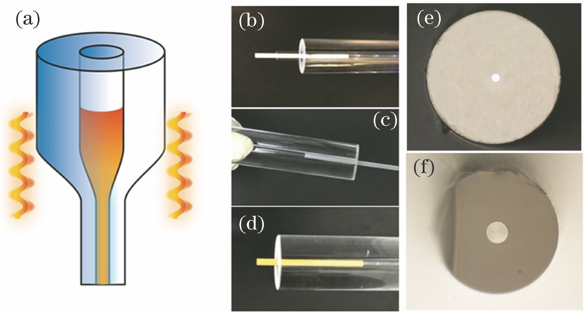
Fig. 1. Fabrication of optical fiber by melt-in-tube method. (a) Diagram of fiber drawing process; (b)-(d) fiber preforms based on ceramics or crystals; (e)-(f) cross sections of prepared optical fiber
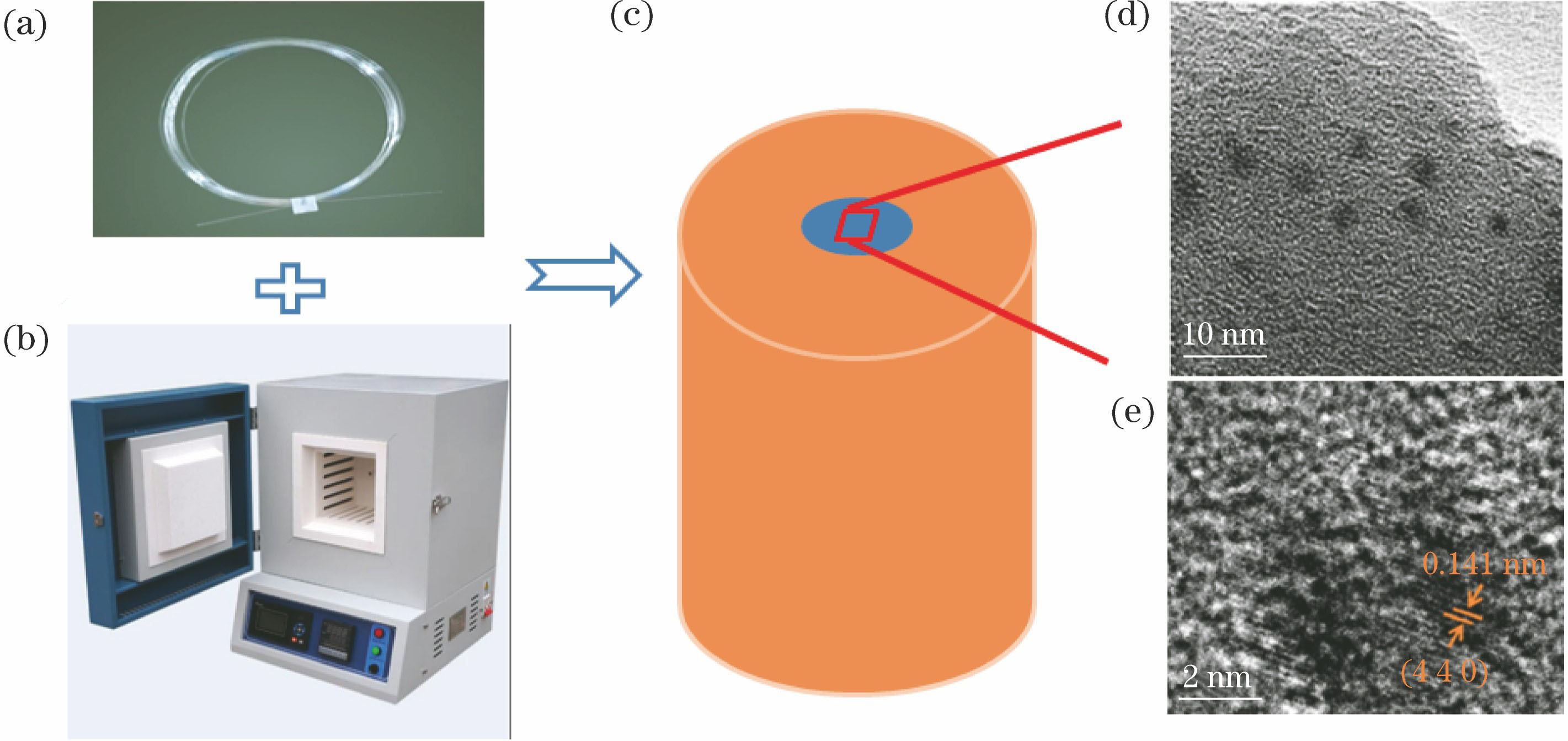
Fig. 2. Main processes for fabricating microcrystalline optical fiber. (a) Drawn precursor fiber; (b) muffle furnace process; (c) microcrystalline optical fiber; (d)(e) nanocrystalline particles with certain size
Fig. 3. Crystallization process in microcrystalline optical fiber by MIT method. (a) Glass rod before drawing process; (b) crystallization appears in bottom after drawing process and glass rod turns to opaque; (c) X-ray diffraction patterns of samples 1#-4# (1# represents uncontrolled crystallized glass rod after drawing, 2# represents glass rod before drawing, 3# represents secondary melted glass after crystallization, 4# represents optical fiber core drawn by MIT method, and insert is opaque glass aft
Fig. 4. Laser processing on optical fibers. (a) Diagram of laser post-processing on optical fiber; (b) temperature distributions of fiber after laser irradiation
Fig. 5. In-situ chemical reaction in fiber drawing process. (a)(b) Chemical reaction and element migration during drawing process; (c)-(e) changes of core composition in different stages of fiber drawing process
Fig. 6. Semiconductor fiber connected with silica optical fiber network. (a) Coupling of spatial optical light and tapered semiconductor core optical fiber; (b) coupling of tapered semiconductor core optical fiber and single-mode fiber
Fig. 7. Laser applications of YAS fiber. (a) Diagram of all-fiber linear cavity based on Tm∶YAS fiber; (b) 2.0 μm laser output spectrum of Tm∶YAS fiber laser; (c) 1.0 μm laser output spectrum of Nd∶YAS fiber laser (insert is near-field energy distribution of home made all-fiber laser); (d) diagram of DBR fiber laser with highly doped Yb∶YAS; (e) longitudinal mode characteristics of single frequency fiber laser
| Preform | Drawing temperature /℃ | Crystallization temperature /℃ | Application /performance | Transmission loss /(dB·m-1) | Reference |
|---|
| | Core (glass) | Cladding |
|---|
| 60.9SiO2-16Al2O3-16ZnO-7TiO2-0.1Cr2O3 | Silica tube | 1830 | 850 | Broadband emission in 600-800 nm | - | [15] | | 64SiO2-23Ga2O3-13Li2O-0.1NiO | Silica tube | 1830 | 800 | Broadband emission in near infrared | - | [16] | | 25.5Li2O-21.5Ta2O5-35.3SiO2-17.6Al2O3-0.15NiO | Silica tube | 1950 | 800 | Broadband emission in 1140-1620 nm | - | [17] | | 60B2O3-8Bi2O3-32CaF2-1YbF3-0.5ErF3 | Commercial BK7 glass tube | 1000 | 530 | 100 times upconversion luminescence enhancement | - | [10] | | 45SiO2-5Al2O3-35BaO-15TiO2 | Silica tube | 1830 | 850 | Second harmonic effect | 8.1(@532 nm) | [11] | | 37B2O3-28SiO2-18Na2O-7NaF-10YF3-2ErF3-xHoF3(x=0, 1, 2, 3) | Commercial BK7 glass tube | 950 | 470-500 | Mid-infrared emission in 2.6-2.95 μm | 11.3(@1310 nm) | [12] | | 40B2O3-25SiO2-18Na2O-7NaF-10YF3-2ErF3 | Commercial BK7 glass tube | 950 | 470-500 | Enhanced emission in 2.7 μm | 7.4(@1310 nm) | [18] | | 66SiO2-8B2O3-18K2O-6ZnO-2ZnS-1PbO | Silica tube | 1830 | 560-600 | Broadband luminescence in 1-2 μm | - | [13] | | 1*: 52B2O3-15Na2O-15K2O-13ZnO-5Al2O3-1PbO-1ZnS2*:25SiO2-35B2O3-25Na2O-10ZnO-5BaO-1PbO-1ZnS | 1*: commercial borosilicate glass tube #12*: commercial borosilicate glass tube #2 | 1*:10002*: 950 | 390-410 | Controllable grain sizecorresponds to tunable 1.0-1.8 μm emission | 14.4-27.1(@1310 nm) | [19] | | 50SiO2-30GeO2-15MgO-5Al2O3-1.0Bi2O3 | Silica tube | 1830 | - | Broadband emission in near infrared | 6.9(@1310 nm) | [14] | | SrO/Al2O3(5∶8 in mol) | Silica tube | 1925 | - | ≈0 brillouin frequency thermal coefficient | 2.7(@1534 nm) | [20] | | SrF2/Al2O3 powder | Silica tube | 2000 | - | Low intrinsic nonlinearity | 0.7-2.7(@1534 nm) | [21] |
|
Table 1. Optical fiber with glass core
| Preform | Drawing temperature /℃ | Application performance | Transmission loss /(dB·cm-1) | Reference |
|---|
| | Core | Cladding |
|---|
| Bi2Se3 powder | Commercial K9 glass | 840 | Thermoelectric performance | - | [31] | | Se/Te powder(1∶1 in mol) | Multicomponent phosphate glass | 660 | Stress sensing/optical detection | 2.6(@1310 nm) | [32] | | Sb2Se3 powder | Multicomponent phosphate glass | 660 | Temperature sensor photoelectric detector | - | [33] | | Se/Te powder(4∶1 in mol) | Multicomponent phosphate glass | 660 | Optical switch and photoelectric detector | 2.0(@1550 nm) | [24] | | Te powder | Multicomponent phosphate glass | 660 | Far infrared/terahertz waveguide | Too high | [25] | | In/Se powder(4∶3 in mol) | Commercial borosilicate glass tube | 900 | Thermoelectric integrated | - | [34] | | Bi2Te3 powder | Commercial borosilicate glass tube | 900 | Thermoelectric optical fiber | - | [35] | | SnSe powder | Commercial borosilicate glass tube | 900 | Thermoelectric integrated | - | [36] | | Al rod | Silica tube | 2200 | Crystalline silicon fiber | - | [29] | | GaSb pellet | Duran glass tube AR glass tube | Torch flame/laser processing | Near infrared photoluminescence/adjustable band gap | - | [37] | | Silicon rod/CaO coating | Silica tube | Oxyacetylene flame | Nonlinear photonics applications in infrared | 1-2.5(1500-2500 nm) | [38] | | Silicon rod/oxide coating | Silica tube | Oxyacetylene flame | 3.8-20(@1550 nm) | [28] |
|
Table 2. Optical fiber with semiconductor core
| Preform | Drawing temperature /℃ | Application performance | Transmission loss /(dB·m-1) | Reference |
|---|
| | Core (rod) | Cladding |
|---|
| Cr∶YAG | Silica tube | 2025 | Near infrared broadband amplification in 1.2-1.6 μm | 20(@1550 nm) | [39] | | Er∶YAG | Silica tube | 2025 | Emission similar to erbium doped fiber amplifier (EDFA) higher doping concentration | 0.15-0.2(@1300 nm) | [44] | | Yb∶YAG | Silica tube | 2000 | Reduced stimulated Brillouin | 0.1(@1.3 μm) | [45] | | Yb∶YAG | Silica tube | 2000 (post feeding) | ≈4 W laser output | 2.2(@1200 nm) | [46] | | Nd∶YAG | | Silica tube | 1.5(@1200 nm) | [47] | | Nd∶YAG | Silica tube | 2000 | Low threshold all-fiber laser | 8.2(@1550 nm) | [48] | | Tm∶YAG | Silica tube | 2000 | Fiber laser in 2 μm | 9.2(@1550 nm) | [49] | | Yb∶YAG | Silica tube | 2000 | Single-frequency laser output | 5.6(@1550 nm) | [40] | | Yb∶YAG/Al2O3 | Silica tube | 2000 | High nonlinearity low Brillouin gain | 0.7(@1550 nm) | [50] | | Al2O3 | Silica tube | 2100 | Ultra-low Brillouin gain | 0.2(@1534 nm) | [41] | | LuAG | Silica tube | 2025 | Sensitive stress sensing | 1.5(@1534 nm) | [42] | | MgAl2O4 | Silica tube | 2175 | Highly acoustically-anti-guiding waveguide properties | 0.2(@1534 nm) | [43] |
|
Table 3. Optical fiber with crystal core