
Yi Liu, Chunmei Ouyang, Quan Xu, Xiaoqiang Su, Quanlong Yang, Jiajun Ma, Yanfeng Li, Zhen Tian, Jianqiang Gu, Liyuan Liu, Jiaguang Han, Yunlong Shi, Weili Zhang. Moiré-driven electromagnetic responses and magic angles in a sandwiched hyperbolic metasurface[J]. Photonics Research, 2022, 10(9): 2056
- Photonics Research
- Vol. 10, Issue 9, 2056 (2022)
Abstract
1. INTRODUCTION
Recent advances in nanofabrication techniques, such as direct writing [1,2], nanoimprinting [3], lithography [4–6], and assembly approaches [7–11], have promoted the development of moiré metamaterials and metasurfaces, which have enabled numerous distinctive phenomena and unique light–matter interactions. Moiré effects in reciprocal space, existing in bilayer graphene [12–17], [18,19], van der Waals materials [20–23], nanosphere superlattice [24,25], and other dielectric nanophotonic materials [26,27], result in abundant exotic electronic properties and optical features—for instance, superconductivity [28–30], ferromagnetism [31–35], extreme dispersion engineering [36–39]—which allow unprecedented capabilities in the applications of optical chirality [40,41], full-wave manipulation [36], quantum responses [42–44], phonon polaritons [45–47], etc. Interestingly, new symmetries emerge from stacking and twisting, causing hybridization of dispersions, which enables drastic surface state manipulation [48,49]. However, previous works are mostly concentrated on moiré patterns in variable frequency regimes ranging from UV to visible and to infrared (IR) [50–52], and moiré topological transitions of surface states based on twisted hyperbolic metasurfaces (HMSs) at microwave and terahertz frequencies remain unexplored. Since there is no efficient terahertz dipole source to experimentally verify the twist-induced dispersion engineering, we designed a moiré hyperbolic metasurface (MHMS) in the microwave regime to emulate the moiré phenomena. One prominent advantage is the much simpler fabrication process of microwave HMSs than the complicated nanolithography techniques in the UV-IR range [53,54]; another advantage is that the rotation angle between the two relatively independent periodic metasurfaces can be easily and precisely controlled.
Classical plasmonics aims at exploring the fundamental properties of surface plasmon polaritons (SPPs), which describe the confined electromagnetic wave propagation along the interface between a metal and dielectric [55]. However, because metals can be regarded as perfect electric conductors in the microwave region, the SPPs become weakly confined Zenneck waves and the evanescent fields can extend over several wavelengths [56]. Therefore, structured metals are utilized to overcome the limits, and microwave plasmonics composed of subwavelength metal patterns and dielectric slabs can exhibit unique topological transition and have been widely used to manipulate surface waves [57]. For example, planarized sandwich and dielectric-metal structures can be used to obtain the hyperbolic dispersion in the momentum space by varying the permittivity or the structural parameters [58–62]. Topological transitions only occur at a specific excitation frequency, which greatly limits their applications. Nevertheless, moiré effects can arise when mutual rotation is introduced to a stacked bilayer HMS, inducing hyperbolic-to-elliptic topological transitions in the whole frequency range due to the twist-induced coupling between two adjacent layers. Such a photonic phase transition in the equal-frequency contours (EFCs) is analogous to the Lifshitz transition in electronics [63], and the nondiffraction transmission in photonic systems is similar to the dissipation-free flow of electrons (superconductivity). Therefore, the MHMS experiences a topology change after stacking and twisting, and, at the critical angle where the photon density of states reaches a maximum, the dispersion behaves as a flat line, and the angle is thus referred to as the magic angle [64,65]. The flexibility in designing moiré patterns and the sensitivity to rotation-induced dispersion responses allow for on-demand surface wave modifications. The proposed regime offers a new avenue to break the diffraction limits, applicable to nondivergent diffraction [66], negative diffraction [67], and anomalous wave propagation [68,69].
In this paper, we demonstrate theoretically, numerically, and experimentally moiré topological transitions in a sandwiched metal metasurface consisting of two closely stacked periodic hyperbolic microstructures rotated relative to each other. The photonic responses can be actively controlled by rotating the angle between the two stacked layers, leading to hybridization of the EFCs and moiré effects. To fully investigate the underlying mechanism of the numerous wave features, a Fourier transform is employed to map the corresponding iso-frequency lines controlled by the rotation angles. These unusual moiré phenomena emerge as a result of eigenmode coupling and the MHMS formation, presenting an evolution of dispersion from being hyperbolic to elliptical, which facilitates active engineering of surface waves. Besides, at the magic angles, the number of anti-intersection points between the coupled system and the individual layers can be applied to separate the EFCs with different shapes, where has a discontinuous change. Finally, we fit the function between the magic angles and frequencies, observing that the magic angle changes linearly with frequency, proving that the MHMS can realize topological transition at each frequency. The proposed MHMS offers a new platform to manipulate light-propagation properties and is therefore promising for nonlinear optics [70,71], near-field focusing [72,73], imaging [74,75], etc.; it also shows exceptional capabilities in designing plasmonic devices, multifunctional devices, and sensors.
Sign up for Photonics Research TOC. Get the latest issue of Photonics Research delivered right to you!Sign up now
2. SIMULATION AND DISCUSSION
A. Structural Design
As shown in Fig. 1, a moiré structure is formed by stacking two mutually twisted H-shaped periodic HMSs, which consist of a lossless substrate () with a permittivity of 3.0 and an anisotropic copper pattern. Compared with other microwave HMSs, the H-shaped ultrathin meta-array exhibits an excellent ability to manipulate surface waves. The detailed structural parameters of the unit cell are designed as , , , and ; the thicknesses of the dielectric substrate and the copper structure are 1 and 0.035 mm, respectively. The relative rotation angle is defined as the anticlockwise rotation of the top layer with respect to the bottom layer. A microwave dipole resonating in the direction is placed at the center of the designed MHMS to excite surface waves. When the superimposed top layer rotates relative to the bottom layer, a drastic plasmon hybridization effect between the two HMSs occurs due to the strong anisotropy of the monolayers. Therefore, the coupling of eigenmodes between the two layers will change the shape and intensity of the surface waves when a misalignment of the optical axes between the two layers appears, thereby enabling the manipulation of surface plasmons. As also depicted at the top right in Fig. 1, topological transitions of the surface states appear as the rotation angle increases (from a V-shaped pattern to a flattened line and finally to a spherical trajectory), which will provide new degrees of freedom for the engineering of light–matter interactions and present great potential in designing active plasmonic devices.
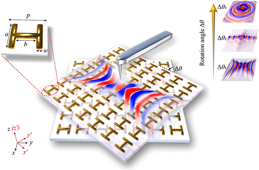
Figure 1.Schematic diagram of the designed MHMS, where the structural parameters of a unit cell (inset at the top left) are set as
B. Basic Physical Properties
1. Dispersion Characteristics of the Monolayer Hyperbolic Metasurface
Previous studies are mostly concerned with the tight-binding approximation to express the -space properties [39]; here, the effective medium theory (EMT) is utilized to describe the moiré configurations in the microwave region. Therefore, in order to analyze the SPP redirection effect of the proposed MHMS, we start with the electromagnetic characteristics of the designed individual monolayer HMS using the time-domain solver of the commercial software Computer Simulation Technology (CST). As depicted in Fig. 2(a), the transmission spectra have Lorentzian profiles, which are symmetrically shaped lines when the incident waves are polarized in the and directions. Figures 2(b) and 2(c) exhibit greatly different electric distributions when the plane waves propagate along the and axes, respectively. These results provide insight into the electric dipoles in the orthogonal directions induced by the incident polarization states; they also indicate that the model has a strong anisotropic response. Furthermore, we built equivalent circuit models to describe the electric dipoles with a dipole moment along the and directions, respectively. As presented in Figs. 2(d) and 2(e), the resonance frequencies are and . Besides, we employed the EMT to simplify the designed monolayer HMS to a homogeneous anisotropic effective-medium slab. For the nonmagnetic uniaxial material whose permeability mainly comes from the metal patterns, it is reasonable to set as an approximation; the permittivity can also be reduced to a diagonal tensor, , where and can be obtained by the -parameter retrieval process [76–78]. According to Snell’s law, (transmittance) and (reflectance) are related to the effective refractive index and the impedance of the dielectric slab by
![]()
Figure 2.Electromagnetic properties of the individual HMS. (a) Normalized transmittance and reflectance spectra when the incident waves are polarized in the
The calculated permittivity is plotted in Fig. 2(f), where the gray areas represent the hyperbolic EFCs and topological transition frequencies (8.63 and 19.49 GHz). The structure corresponds to a type II HMS for , where and ; when , the structure has the characteristics of a type I HMS with and . As the surface wave transmits in the direction perpendicular to the EFC, nondiffraction transmission occurs at the transition frequencies in two perpendicular directions, and the detailed dispersion properties of the H-shaped single-layer structure are investigated through CST eigenvalue analysis in the following.
Assuming that the electromagnetic waves propagate in the plane and decay along the direction, the dispersion relation can be calculated by substituting the permittivity tensor into Maxwell’s equations as follows:
2. Dispersion Characteristic of the Bilayer Hyperbolic Metasurface
Since the thickness of the MHMS is much smaller than the wavelength, the bilayer HMS can be treated as a single layer with period when [80]. Based on the EMT, the model can still be regarded as a homogeneous anisotropic effective-medium slab whose permittivity is a diagonal tensor. However, the stacking between different layers will excite magnetic modes manifesting as ring-like surface current distributions in the split rings [see Figs. 3(h)–3(k)]; hence, the polaritons in the MHMS change from TM modes to hybrid TM and TE eigenmodes and the permeability becomes a diagonal tensor as well. In general, conductivity is introduced to describe the dispersion relation: , . The total electric and magnetic fields can be written as the summation of the corresponding components of pure TE and TM modes: , . According to the electromagnetic boundary conditions, the dispersion relation of the surface waves is written as [81]
![]()
Figure 3.Electromagnetic properties of the proposed bilayer HMS when
As exhibited in Fig. 3, by analyzing the transmittance and reflectance curves under - and -polarized incidence, we obtain the following conclusions from the effective permittivity and permeability data [Figs. 3(b) and 3(c)]. 1) The topological transition frequencies decrease because of the presence of new resonance valleys (6.59 and 8.63 GHz when the incident wave is polarized in the direction; 14.60 and 19.30 GHz when the electric field is polarized in the direction) with lower frequencies. 2) The increase of coupling modes causes an increase in the number of topological transition frequencies, and obvious transition occurs at 6.39, 8.57, and 19.09 GHz. 3) The three gray regions (6.39–6.70, 8.57–8.99, and 19.09–22.04 GHz) correspond to type II HMS, type II HMS, and type I HMS, respectively. As the surface plasmon group velocity is perpendicular to the EFC, the directions of the self-collimation frequencies are along the , , and axes, respectively. 4) Compared with the monolayer structure, the relative permeability tensor changes from a unit matrix to a diagonal one, which means that magnetic responses appear as a result of stacking. Analogously, the resonance dips represent similar electric distributions, which show the same excited modes, as shown in Figs. 3(d)–3(g). 5) Finally, the calculated energy band diagram and the first two EFCs in the first Brillouin zone show the same phenomena as the relative permittivity predicted above [see Figs. 3(l)–3(n)].
3. Dispersion Characteristic of the Twisted Bilayer Hyperbolic Metasurface
The MHMS turns to an aperiodic structure when , where the relative permittivity and permeability change from diagonal tensors to fully populated tensors owing to the rotation and stacking. We can, however, still use Eq. (5) to characterize the dispersion relations of the MHMS. Appendix B studies the corresponding conductivity tensors of the twisted bilayer hyperbolic metasurface. Then, taking as an example, we simulated the co- and cross-polarized transmittance and reflectance spectra [Figs. 4(a) and 4(b)] to obtain the nondiagonal terms of the relative permittivity and permeability. The appearance of the cross-polarization (the orange and blue solid lines) means that the proposed MHMS has the ability for polarization conversion, which has great potential in the active control of metasurfaces and will enrich the multifunctional devices. Based on the -parameter retrieval process, the corresponding calculated results of the real and imaginary parts of the relative permittivity and permeability are plotted in Figs. 4(c) and 4(d), respectively. It is clear that the relative rotation between the two HMSs leads to nondiagonal components, which means that the topological transition frequencies and hyperbolic characteristics cannot be simply obtained based on the relative permittivity. Thus, we obtain the EFCs of the MHMS by analyzing the Fourier transform of the distributions in the following part.
![]()
Figure 4.Electromagnetic properties of the proposed MHMS when
3. MOIRÉ HYPERBOLIC METASURFACE
As presented in Fig. 5(a), a moiré pattern is assembled by two H-shaped bilayer metasurfaces with a subwavelength thickness (total size ), and the individual layers have the same parameters and are placed closely to each other in the direction, where the top layer is twisted counterclockwise with respect to the bottom layer by . The CST time-domain solver is used to simulate the distributions at 0.05 mm above the top layer, with the dipole source resonating in the direction and located at the center of the designed model. Interestingly, it is found that the mode hybridization controlled by rotation enhances the electromagnetic response of the MHMS and achieves effective modulation of the topological transition of the surface waves at different frequencies. To illustrate the underlying mechanism of the moiré properties, we numerically calculated the electric field distribution and the corresponding dispersion, which shows that a distinct topological transition occurs with an increase of the relative twist angle. In addition, we observe an obvious electric field enhancement by about at 0.5 mm above the metasurface, which will provide a new route to construct detectors with enhanced sensitivity [82].
![]()
Figure 5.Twist-induced topological transition of surface plasmons. (a) Schematic illustration of the proposed MHMS, where the top layer is rotated counterclockwise with respect to the bottom layer. (b) At 5.90 GHz,
With the -oriented electric field distributions at 5.90 GHz taken as an example, the Fourier transform is utilized to map the corresponding EFCs [see Figs. 5(b) and 5(c)]. In the reciprocal space, the white solid curves are the fitted dispersion contours, while the red and yellow dotted curves are the EFCs of the top and bottom layers, respectively, and the red arrows denote the directions of the wave vectors. When , the surface waves propagate along a convergent path, and the resulting EFC is a hyperbola. When , the excited SPPs transmit along a nondiffraction collimated path, which means that the corresponding EFC is a tilted flattened line. When , the trajectory of polariton propagation exhibits a V-shape, which originates from the elliptical EFC. When , the EFC is a closed circle, leading to a spherical expanding wavefront. Besides, it can be found that the anti-intersection points () can be used to qualitatively characterize the moiré topological transition angle: when , the resulting dispersion is hyperbolic, but, when , the dispersion turns into an ellipse, where the moiré topological transition occurs.
To further demonstrate the varying pattern of the magic angle, we summarize the change of the topological transition frequencies with respect to the rotation angles, as illustrated in Fig. 5(d). The black dotted line denotes the magic angles that separate the range of hyperbolic (the blue area, ) and elliptical dispersion (the orange area, ). Therefore, the designed moiré structure makes a topological transition at an arbitrary frequency possible by merely controlling the twist angle, showing great potential in multifunctional devices and integrated plasmonic devices and promising a new platform to manipulate diverse surface plasmon transmission processes. In addition, the number of anti-intersection points, , in the -space directly determines the shape of the dispersion contour. When changes discontinuously, the EFCs change simultaneously, from a closed ellipse to an open hyperbola, resulting in a magic angle topological transition due to enhanced light–matter interactions and coupling between the individual isolated layers. Detailed descriptions about the magic angles are given in Appendix C. In addition, the spacer thickness dependence of the moiré structure is discussed in Appendix D to further investigate the electromagnetic interaction. In a word, the proposed MHMS, in which the superimposed layer is rotated with respect to the bottom layer, enables the observation of polariton hybridization, drastic dispersion modifications, and highly tunable optical responses.
4. EXPERIMENTAL RESULTS
The experimental sample was composed of two identical H-shaped HMSs with a twisted angle between them. A 1 mm thick was employed as the dielectric substrate with a permittivity of 3.0 and tan at 10 GHz, and a 0.035 mm thick H-shaped copper pattern was printed on the substrate slab, as shown in Fig. 6. Besides, the organic solderability preserving anti-oxidation process was carried out on the metal surface to facilitate long-term experimental measurement needs. The constructed monolayer was chosen with the following geometries: , , , and ; the total size was . Since the coupling between free-space radiation and the HMSs was extremely weak, a probe connected with a vector network analyzer was placed close to the center of the copper pattern to excite a microwave dipole and improve the coupling efficiency. In order to shield the spatial electromagnetic signal radiated by the dipole source during the experiments, we used a metal box with a small round hole on the top to localize the dipole in the box, which could not only reduce the radiation loss of the electromagnetic waves but also enhance the coupling between the copper pattern and the impinging wave. Another probe was used to detect the field distributions located at 0.05 mm above the surface, being moved with a step of 2 mm along the and axes by a 3D translation stage.
![]()
Figure 6.Top view of the experimental process. A vector network analyzer was employed to generate the excitation signals; the 3D movement platform detected the
Taking into account the symmetry of the electric fields on both sides of the source, we selected the right half of the model (red dotted area) as the fine scanning range, as depicted in Fig. 7(a). Similarly, to experimentally observe the topological transition of the twist-induced surface states, we mapped the distributions at 6.53 GHz in Fig. 7(b). Interestingly, when , we observed a nondiffraction transmission of surface waves at their self-collimation frequencies where the photon density of states is relatively large, and the localization of surface waves is strong. Unlike at other angles, the electric field pattern turns from a straight trajectory into a spherical wavefront when . That is, with the increase of the mutually twisted angle, the dispersion changes from an open hyperbola to a closed ellipse based on the rule that the transmission direction of surface waves is perpendicular to the EFC. The corresponding Fourier transform of the experimental results is performed in Appendix E, which exhibits the same topological transition process as the simulation results. However, in the measurement process, the unevenly distributed electric fields and deviation in the rotation angles mainly come from the fabrication error and height difference of the MHMS. But our experimental results are also numerically supported by our simulations with excellent agreement. In addition, other structured hyperbolic metasurfaces and magnetic topological transition configurations with double split-rings may provide new methods to reduce the propagation loss.
![]()
Figure 7.Experimental verifications of SPP propagation in the MHMS. (a) Detail of the measurement process, including the microwave dipole source and the scanning range (red dotted area). (b) At 6.53 GHz, measured
We then summarized the relationship between the magic angle and the frequency in Fig. 7(c); it can be seen that the magic angle changes linearly with frequency, as shown by the black dotted line, and the dispersion is hyperbolic below the line and elliptic above. The magic angle observed at the topological transition point offers a new avenue for engineering light–matter interactions and optical responses. Different from previous methods based on sweeping the topological transition frequencies in different structures, the proposed regime can realize the control of surface states at arbitrary frequencies.
5. CONCLUSION
A new type of sandwiched twisted bilayer metal hyperbolic metasurface is proposed, which enables the steering of electromagnetic responses (the evolution process of the relative permittivity and permeability tensors) and the excitation of magic angle phenomena (drastic dispersion modification) by the relative rotation of the superimposed layer. The designed MHMS can realize topological transitions at arbitrary frequencies rather than a single transition frequency compared with a monolayer counterpart. Besides, Fourier transform of the real space is introduced to study the underlying mechanism of the surface states with the increase of the twist angles. In particular, the fitted curve of the magic angles separating the closed (ellipse) and open (hyperbola) dispersion contours changes linearly with frequency, and the position of the magic angles can be found quantitatively by calculating the number of anti-intersection points between the moiré structure and the distinct layers. Finally, experimental measurements are implemented to verify the interesting twist-induced moiré effects, and the results are in good agreement with the simulations. The proposed MHMS provides a unique way to manipulate light propagation properties and offers new opportunities in designing plasmonic devices, which can be widely used in sensing, imaging, and slow light applications in the microwave region [82].
APPENDIX A: CONDUCTIVITY TENSORS OF THE BILAYER HYPERBOLIC METASURFACE
Assuming that the surface plasmons transmit along the direction, we built a rotated coordinate system () to make coordinate transformation for the conductivity tensors of the top and bottom layers, as shown in Fig.
![]()
Figure 8.Schematic diagram of the bilayer hyperbolic metasurface. The coordinate systems of the bottom layer and top layer are set as
APPENDIX B: CONDUCTIVITY TENSORS OF THE TWISTED BILAYER HYPERBOLIC METASURFACE
In order to calculate the conductivity tensors of the twisted bilayer hyperbolic metasurface, the rotation matrix is adopted to describe the conductivity of the superimposed layer when the metasurface rotates counterclockwise at an angle around the axis (see Fig.
![]()
Figure 9.Schematic diagram of the proposed moiré metasurface. Similar to Fig.
Similarly, a new coordinate system () is employed to make a transform:
APPENDIX C: SIMULATED AND MEASURED FIELD DISTRIBUTIONS AT DIFFERENT MAGIC ANGLES
In order to explain the magic angle curve more clearly, we numerically and experimentally investigated the field distributions at the topological transition frequencies for different mutual rotation angles, as there exist independent self-collimation frequencies at each rotation angle. As shown in Figs.
![]()
Figure 10.(a), (b) Simulated and measured
APPENDIX D: SPACER THICKNESS DEPENDENCE OF THE MOIRé STRUCTURE
To further investigate the electromagnetic interaction in the stacked bilayer hyperbolic metasurface, we discuss the spacer thickness dependence of the moiré structure. As shown in Fig.
![]()
Figure 11.Tunable dispersion of the bilayer structure by changing the inter-stack distance. (a) Schematic illustration of the bilayer metasurface where the top and bottom layers are separated by
APPENDIX E: DISPERSION PROPERTIES OF THE EXPERIMENTAL SAMPLE AT DIFFERENT MAGIC ANGLES
As depicted in Fig.
![]()
Figure 12.Dispersion contours of the measured
References
[1] N. G. Semaltianos, K. Scott, E. G. Wilson. Electron beam lithography of Moiré patterns. Microelectron. Eng., 56, 233-239(2001).
[2] B. Chen, K. Lu. Moire pattern nanopore and nanorod arrays by focused ion beam guided anodization and nanoimprint molding. Langmuir, 27, 4117-4125(2011).
[3] A. Espinha, C. Dore, C. Matricardi, M. I. Alonso, A. R. Goñi, A. Mihi. Hydroxypropyl cellulose photonic architectures by soft nanoimprinting lithography. Nat. Photonics, 12, 343-348(2018).
[4] S. M. Lubin, W. Zhou, A. J. Hryn, M. Huntington, T. W. Odom. High-rotational symmetry lattices fabricated by moiré nanolithography. Nano Lett., 12, 4948-4952(2012).
[5] S. Balci, A. Kocabas, C. Kocabas, A. Aydinli. Localization of surface plasmon polaritons in hexagonal arrays of moiré cavities. Appl. Phys. Lett., 98, 031101(2011).
[6] A. Kocabas, S. S. Senlik, A. Aydinli. Slowing down surface plasmons on a moiré surface. Phys. Rev. Lett., 102, 063901(2009).
[7] C. Kai, B. B. Rajeeva, Z. Wu, M. Rukavina, T. D. Dao, S. Ishii, M. Aono, T. Nagao, Y. Zheng. Moirè nanosphere lithography. ACS Nano, 9, 6031-6040(2015).
[8] V. Luchnikov, A. Kondyurin, P. Formanek, H. Lichte, M. Stamm. Moiré patterns in superimposed nanoporous thin films derived from block-copolymer assemblies. Nano Lett., 7, 3628-3632(2007).
[9] C. Jin, B. C. Olsen, E. J. Luber, J. M. Buriak. Preferential alignment of incommensurate block copolymer dot arrays forming Moiré superstructures. ACS Nano, 11, 3237-3246(2017).
[10] A. Singh, C. Dickinson, K. M. Ryan. Insight into the 3D architecture and quasicrystal symmetry of multilayer nanorod assemblies from moiré interference patterns. ACS Nano, 6, 3339-3345(2012).
[11] Y. He, S. H. Ko, T. Ye, A. E. Ribbe, C. Mao. Complexity emerges from lattice overlapping: implications for nanopatterning. Small, 4, 1329-1331(2008).
[12] R. Bistritzer, A. H. Macdonald. Moire bands in twisted double-layer graphene. Proc. Natl. Acad. Sci. USA, 108, 12233-12237(2011).
[13] S. Sunku, G. Ni, B.-Y. Jiang, H. Yoo, A. Sternbach, A. McLeod, T. Stauber, L. Xiong, T. Taniguchi, K. J. Watanabe. Photonic crystals for nano-light in moiré graphene superlattices. Science, 362, 1153-1156(2018).
[14] G. Chen, A. L. Sharpe, P. Gallagher, I. T. Rosen, E. J. Fox, L. Jiang, B. Lyu, H. Li, K. Watanabe, T. Taniguchi. Signatures of tunable superconductivity in a trilayer graphene moire superlattice. Nature, 572, 215-219(2019).
[15] C. Mora, N. Regnault, B. A. Bernevig. Flatbands and perfect metal in trilayer moiré graphene. Phys. Rev. Lett., 123, 026402(2019).
[16] G. X. Ni, H. Wang, J. S. Wu, Z. Fei, M. Goldflam, F. Keilmann, B. Özyilmaz, A. C. Neto, X. M. Xie, M. M. Fogler. Plasmons in graphene moiré superlattices. Nat. Mater., 14, 1217-1222(2015).
[17] H. Z. Zhang, H. Y. Qin, W. X. Zhang, L. Huang, X. D. Zhang. Moiré graphene nanoribbons: nearly perfect absorptions and highly efficient reflections with wide angles. Opt. Express, 30, 2219-2229(2022).
[18] Q. Zhang, Q. Ou, G. Hu, J. Liu, Z. Dai, M. S. Fuhrer, Q. Bao, C.-W. Qiu. Hybridized hyperbolic surface phonon polaritons at α-MoO3 and polar dielectric interfaces. Nano Lett., 21, 3112-3119(2021).
[19] G. Hu, Q. Ou, G. Si, Y. Wu, A. Alù. Topological polaritons and photonic magic angles in twisted α-MoO3 bilayers. Nature, 582, 209-213(2020).
[20] K. Tran, G. Moody, F. Wu, X. Lu, J. Choi, K. Kim, A. Rai, D. A. Sanchez, J. Quan, A. Singh. Evidence for moiré excitons in van der Waals heterostructures. Nature, 567, 71-75(2019).
[21] N. Leconte, J. Jung, S. Lebègue, T. Gould. Moiré-pattern interlayer potentials in van der Waals materials in the random-phase approximation. Phys. Rev. B, 96, 195431(2017).
[22] E. M. Alexeev, D. A. Ruiz-Tijerina, M. Danovich, M. J. Hamer, D. J. Terry, P. K. Nayak, S. Ahn, S. Pak, J. Lee, J. I. Sohn. Resonantly hybridized excitons in moiré superlattices in van der Waals heterostructures. Nature, 567, 81-86(2019).
[23] G. Hu, J. Shen, C. W. Qiu, A. Alù, S. Dai. Phonon polaritons and hyperbolic response in van der Waals materials. Adv. Opt. Mater., 8, 1901393(2020).
[24] F. He, Y. Zhou, Z. Ye, S.-H. Cho, J. Jeong, X. Meng, Y. Wang. Moiré patterns in 2D materials: a review. ACS Nano, 15, 5944-5958(2021).
[25] H. N. Barad, H. Kwon, M. Alarcón-Correa, P. Fischer. Large area patterning of nanoparticles and nanostructures: current status and future prospects. ACS Nano, 15, 5861-5875(2021).
[26] S. Takahashi, T. Tajiri, Y. Ota, J. Tatebayashi, S. Iwamoto, Y. Arakawa. Circular dichroism in a three-dimensional semiconductor chiral photonic crystal. Appl. Phys. Lett., 105, 051107(2014).
[27] J. Lee, C. T. Chan. Circularly polarized thermal radiation from layer-by-layer photonic crystal structures. Appl. Phys. Lett., 90, 051912(2007).
[28] M. Yankowitz, S. Chen, H. Polshyn, Y. Zhang, C. R. Dean. Tuning superconductivity in twisted bilayer graphene. Science, 363, 1059-1064(2019).
[29] Y. Cao, V. Fa Temi, S. Fa Ng, K. Watanabe, T. Taniguchi, E. Kaxiras, P. Jarillo-Herrero. Unconventional superconductivity in magic-angle graphene superlattices. Nature, 556, 43-50(2018).
[30] X. Lu, P. Stepanov, W. Yang, M. Xie, M. A. Aamir, I. Das, C. Urgell, K. Watanabe, T. Taniguchi, G. Zhang. Superconductors, orbital magnets and correlated states in magic-angle bilayer graphene. Nature, 574, 653-657(2019).
[31] A. L. Sharpe, E. J. Fox, A. W. Barnard, J. Finney, K. Watanabe, T. Taniguchi, M. Kastner, D. Goldhaber-Gordon. Emergent ferromagnetism near three-quarters filling in twisted bilayer graphene. Science, 365, 605-608(2019).
[32] C. Repellin, Z. Dong, Y. H. Zhang, T. Senthil. Ferromagnetism in narrow bands of moiré superlattices. Phys. Rev. Lett., 124, 187601(2020).
[33] G. Chen, A. L. Sharpe, E. J. Fox, Y.-H. Zhang, S. Wang, L. Jiang, B. Lyu, H. Li, K. Watanabe, T. Taniguchi. Tunable correlated Chern insulator and ferromagnetism in a moiré superlattice. Nature, 579, 56-61(2020).
[34] C. Tschirhart, M. Serlin, H. Polshyn, A. Shragai, Z. Xia, J. Zhu, Y. Zhang, K. Watanabe, T. Taniguchi, M. Huber. Imaging orbital ferromagnetism in a moiré Chern insulator. Science, 372, 1323-1327(2021).
[35] X. C. Wu, A. Keselman, C.-M. Jian, K. A. Pawlak, C. Xu. Ferromagnetism and spin-valley liquid states in moiré correlated insulators. Phys. Rev. B, 100, 024421(2019).
[36] G. Hu, A. Krasnok, Y. Mazor, C. W. Qiu, A. Alù. Moiré hyperbolic metasurfaces. Nano Lett., 20, 3217-3224(2020).
[37] Q. Zhang, G. Hu, W. Ma, P. Li, A. Krasnok, R. Hillenbrand, A. Alù, C. W. Qiu. Interface nano-optics with van der Waals polaritons. Nature, 597, 187-195(2021).
[38] G. Hu, C. Zheng, J. Ni, C. W. Qiu, A. Alù. Enhanced light-matter interactions at photonic magic-angle topological transitions. Appl. Phys. Lett., 118, 211101(2021).
[39] G. Hu, M. Wang, Y. Mazor, C. W. Qiu, A. Alù. Tailoring light with layered and moiré metasurfaces. Trends Chem., 3, 342-358(2021).
[40] Z. Wu, Y. Zheng. Moiré chiral metamaterials. Adv. Opt. Mater., 5, 1700034(2017).
[41] Z. Wu, Y. Zheng. Moiré metamaterials and metasurfaces. Adv. Opt. Mater., 6, 1701057(2018).
[42] P. Lodahl, S. Mahmoodian, S. Stobbe, P. Schneeweiss, P. Zoller. Chiral quantum optics. Nature, 541, 473-480(2017).
[43] M. Yankowitz, J. Jung, E. Laksono, N. Leconte, B. L. Chittari, K. Watanabe, T. Taniguchi, S. Adam, D. Graf, C. R. Dean. Dynamic band-structure tuning of graphene moiré superlattices with pressure. Nature, 557, 404-408(2018).
[44] Y. H. Zhang, T. Senthil. Bridging Hubbard model physics and quantum Hall physics in trilayer graphene/h–BN moiré superlattice. Phys. Rev. B, 99, 205150(2019).
[45] M. Chen, X. Lin, T. H. Dinh, Z. Zheng, J. Shen, Q. Ma, H. Chen, P. Jarillo-Herrero, S. M. Dai. Configurable phonon polaritons in twisted α-MoO3. Nat. Mater., 19, 1307-1311(2020).
[46] S. Moore, C. Ciccarino, D. Halbertal, L. McGilly, N. Finney, K. Yao, Y. Shao, G. Ni, A. Sternbach, E. Telford. Nanoscale lattice dynamics in hexagonal boron nitride moiré superlattices. Nat. Commun., 12, 5741(2021).
[47] N. C. Hesp, I. Torre, D. Barcons-Ruiz, H. H. Sheinfux, K. Watanabe, T. Taniguchi, R. K. Kumar, F. H. Koppens. Nano-imaging photoresponse in a moiré unit cell of minimally twisted bilayer graphene. Nat. Commun., 12, 1640(2021).
[48] H. N. Krishnamoorthy, Z. Jacob, E. Narimanov, I. Kretzschmar, V. M. Menon. Topological transitions in metamaterials. Science, 336, 205-209(2011).
[49] G. Hu, C. W. Qiu, A. Alù. Twistronics for photons: opinion. Opt. Mater. Express, 11, 1377-1382(2021).
[50] Y. Li, X. Xie, H. Zeng, B. Li, Z. Zhang, S. Wang, J. Liu, D. Shen. Giant Moire trapping of excitons in twisted hBN. Opt. Express, 30, 10596-10604(2021).
[51] W. J. Kort-Kamp, F. J. Culchac, R. B. Capaz, F. A. Pinheiro. Photonic spin Hall effect in bilayer graphene moiré superlattices. Phys. Rev. B, 98, 195431(2018).
[52] X. Chen, X. Fan, L. Li, N. Zhang, Z. Niu, T. Guo, S. Xu, H. Xu, D. Wang, H. Zhang. Moiré engineering of electronic phenomena in correlated oxides. Nat. Phys., 16, 631-635(2020).
[53] P. Huo, S. Zhang, Y. Liang, Y. Lu, T. Xu. Hyperbolic metamaterials: hyperbolic metamaterials and metasurfaces: fundamentals and applications. Adv. Opt. Mater., 7, 1970054(2019).
[54] Z. Guo, H. Jiang, H. J. Chen. Hyperbolic metamaterials: from dispersion manipulation to applications. J. Appl. Phys., 127, 071101(2020).
[55] V. Coello, C. E. Garcia-Ortiz, M. Garcia-Mendez. Classical plasmonics: wave propagation control at subwavelength scale. Nano, 10, 1530005(2015).
[56] K. Wang, D. M. Mittleman. Metal wires for terahertz wave guiding. Nature, 432, 376-379(2004).
[57] J. Pendry, L. Martin-Moreno, F. Garcia-Vidal. Mimicking surface plasmons with structured surfaces. Science, 305, 847-848(2004).
[58] Y. Liu, X. Zhang. Metasurfaces for manipulating surface plasmons. Appl. Phys. Lett., 103, 141101(2013).
[59] C. Hu, X. Wu, R. Tong, L. Wang, Y. Huang, S. Wang, B. Hou, W. Wen. A metasurface with bidirectional hyperbolic surface modes and position-sensing applications. NPG Asia Mater., 10, 417-428(2018).
[60] C. Hu, Z. Li, R. Tong, X. Wu, Z. Xia, L. Wang, S. Li, Y. Huang, S. Wang, B. Hou. Type-II Dirac photons at metasurfaces. Phys. Rev. Lett., 121, 024301(2018).
[61] Y. Yang, L. Jing, L. Shen, Z. Wang, B. Zheng, H. Wang, E. Li, N.-H. Shen, T. Koschny, C. M. Soukoulis, H. Chen. Hyperbolic spoof plasmonic metasurfaces. NPG Asia Mater., 9, e428(2017).
[62] Y. Yermakov, A. A. Hurshkainen, D. A. Dobrykh, P. V. Kapitanova, I. V. Iorsh, S. B. Glybovski, A. A. Bogdanov. Experimental observation of hybrid TE-TM polarized surface waves supported by a hyperbolic metasurface. Phys. Rev. B, 98, 195404(2018).
[63] I. Lifshitz. Anomalies of electron characteristics of a metal in the high pressure region. Phys. JETP, 11, 1130-1135(1960).
[64] A. Kerelsky, L. J. Mcgilly, D. M. Kennes, L. Xian, M. Yankowitz, S. Chen, K. Watanabe, T. Taniguchi, J. Hone, C. Dean. Maximized electron interactions at the magic angle in twisted bilayer graphene. Nature, 572, 95-100(2019).
[65] W. Zhang, D. Zou, Q. Pei, W. He, H. Sun, X. Zhang. Moiré circuits: engineering magic-angle behavior. Phys. Rev. B, 104, L201408(2021).
[66] C. Shang, C. Lu, S. Tang, Y. Gao, Z. Wen. Generation of gradient photonic moiré lattice fields. Opt. Express, 29, 29116-29127(2021).
[67] A. A. High, R. C. Devlin, A. Dibos, M. Polking, D. S. Wild, J. Perczel, N. P. De Leon, M. D. Lukin, H. Park. Visible-frequency hyperbolic metasurface. Nature, 522, 192-196(2015).
[68] P. Zheng, Q. Xu, X. Su, D. Wang, Y. Xu, X. Zhang, Y. Li, Z. Tian, J. Gu, L. Liu. Anomalous wave propagation in topological transition metasurfaces. Adv. Opt. Mater., 7, 1801483(2019).
[69] Z. Guo, H. Jiang, H. Chen. Abnormal wave propagation in tilted linear-crossing metamaterials. Adv. Photon. Res., 2, 2000071(2021).
[70] L. Du, Y. Dai, Z. Sun. Twisting for tunable nonlinear optics. Matter, 3, 987-988(2020).
[71] J. V. Moloney, A. C. Newell. Nonlinear optics. Physica D, 44, 1-37(1990).
[72] H. Yang, X. Cao, F. Yang, J. Gao, S. Xu, M. Li, X. Chen, Y. Zhao, Y. Zheng, S. Li. A programmable metasurface with dynamic polarization, scattering and focusing control. Sci. Rep., 6, 35692(2016).
[73] L. Li, P. Zhang, F. Cheng, M. Chang, T. J. Cui. An optically transparent near-field focusing metasurface. IEEE Trans. Microw. Theory, 69, 2015-2027(2021).
[74] Q. Yang, J. Gu, D. Wang, X. Zhang, Z. Tian, C. Ouyang, R. Singh, J. Han, W. Zhang. Efficient flat metasurface lens for terahertz imaging. Opt. Express, 22, 25931-25939(2014).
[75] L. Li, H. Ruan, C. Liu, Y. Li, Y. Shuang, A. Alù, C.-W. Qiu, T. J. Cui. Machine-learning reprogrammable metasurface imager. Nat. Commun., 10, 1082(2019).
[76] D. Smith, S. Schultz, P. Markoš, C. Soukoulis. Determination of effective permittivity and permeability of metamaterials from reflection and transmission coefficients. Phys. Rev. B, 65, 195104(2002).
[77] X. Liu, T. Starr, A. F. Starr, W. J. Padilla. Infrared spatial and frequency selective metamaterial with near-unity absorbance. Phys. Rev. Lett., 104, 207403(2010).
[78] X. Chen, T. M. Grzegorczyk, B.-I. Wu, J. Pacheco, J. A. Kong. Robust method to retrieve the constitutive effective parameters of metamaterials. Phys. Rev. E, 70, 016608(2004).
[79] R. W. Ziolkowski. Design, fabrication, and testing of double negative metamaterials. IEEE Trans. Antennas Propag., 51, 1516-1529(2003).
[80] M. Cheng, P. Fu, S. Chen. Enhanced and tunable photonic spin Hall effect in metasurface bilayers. J. Opt. Soc. Am. B, 39, 316-323(2022).
[81] O. V. Kotov, Y. E. Lozovik. Hyperbolic hybrid waves and optical topological transitions in few-layer anisotropic metasurfaces. Phys. Rev. B, 100, 165424(2019).
[82] H. Hu, X. Lin, L. J. Wong, Q. Yang, D. Liu, B. Zhang, Y. Luo. Surface Dyakonov–Cherenkov radiation. eLight, 2, 2(2022).

Set citation alerts for the article
Please enter your email address
© Copyright 2018-2021 | Chinese Laser Press. All Rights Reserved 沪ICP备15018463号-20