• Acta Optica Sinica
  • Vol. 41, Issue 1, 0106003 (2021)
Jiajing Tu1、* and Zhaohui Li2、3、**
Author Affiliations
  • 1College of Information Science and Technology, Jinan University, Guangzhou, Guangdong 510632, China
  • 2State Key Laboratory of Optoelectronic Materials and Technologies, Sun Yat-sen University, Guangzhou, Guangdong 510275, China
  • 3Southern Marine Science and Engineering Guangdong Laboratory (Zhuhai), Zhuhai, Guangdong 519000, China
  • show less
    DOI: 10.3788/AOS202141.0106003 Cite this Article Set citation alerts
    Jiajing Tu, Zhaohui Li. Review of Space Division Multiplexing Fibers[J]. Acta Optica Sinica, 2021, 41(1): 0106003 Copy Citation Text show less
    Reasons that make the capacity of single-mode fiber approach Shannon limit. (a) Nonlinear Shannon limit[3]; (b) fiber fuse damage phenomenon[4]; (c) transmission window of fused-silica fibers, where black region represents the standard optical amplification band[5]
    Fig. 1. Reasons that make the capacity of single-mode fiber approach Shannon limit. (a) Nonlinear Shannon limit[3]; (b) fiber fuse damage phenomenon[4]; (c) transmission window of fused-silica fibers, where black region represents the standard optical amplification band[5]
    Comparison of crosstalk between Homo-MCF and Hetero-MCF. (a) Crosstalk of Homo-MCF dependence on bending radius and change of effective index under bending condition; (b) crosstalk of Hetero-MCF dependence on bending radius and change of effective index under bending condition
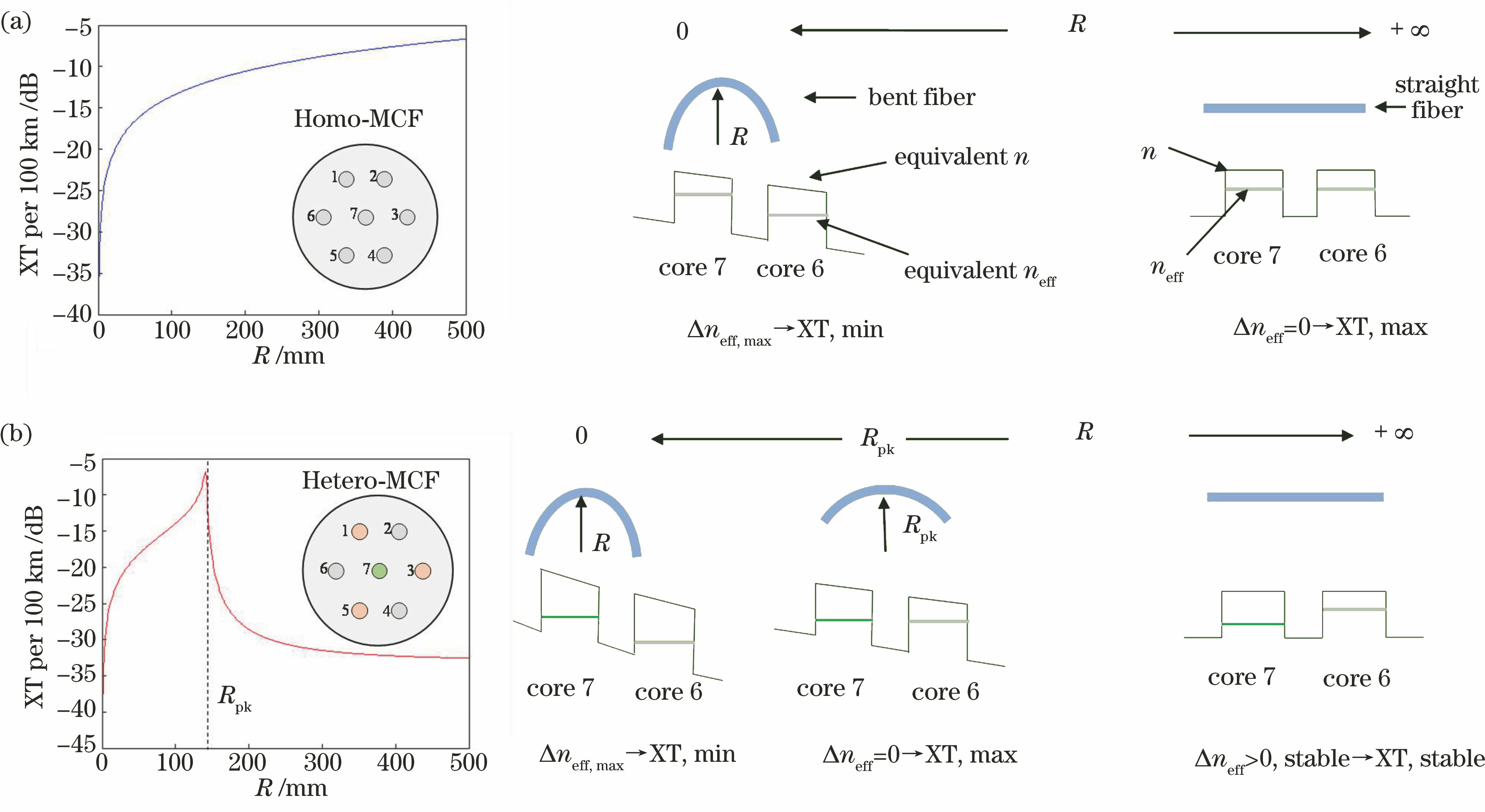
    Fig. 2. Comparison of crosstalk between Homo-MCF and Hetero-MCF. (a) Crosstalk of Homo-MCF dependence on bending radius and change of effective index under bending condition; (b) crosstalk of Hetero-MCF dependence on bending radius and change of effective index under bending condition
    Classification of single-mode multi-core fiber based on the assisted structure around core[20]. (a) Refractive index profile of trench-assisted core; (b) cross-section of trench-assisted multi-core fiber; (c) refractive index profile of air-hole-assisted core; (d) cross-section of air-hole-assisted multi-core fiber; (e) refractive index profile of photonic crystal core; (f) cross-section of photonic crystal multi-core fiber
    Fig. 3. Classification of single-mode multi-core fiber based on the assisted structure around core[20]. (a) Refractive index profile of trench-assisted core; (b) cross-section of trench-assisted multi-core fiber; (c) refractive index profile of air-hole-assisted core; (d) cross-section of air-hole-assisted multi-core fiber; (e) refractive index profile of photonic crystal core; (f) cross-section of photonic crystal multi-core fiber
    Core selection of outer core 1[42]. (a) Cross-section of a Hetero-TA-7-core fiber; (b) neff and Aeff as functions of r1 and Δ1 at λ =1550 nm and Λ=35 μm for the first outer cores in Hetero-TA-7-core fiber
    Fig. 4. Core selection of outer core 1[42]. (a) Cross-section of a Hetero-TA-7-core fiber; (b) neff and Aeff as functions of r1 and Δ1 at λ =1550 nm and Λ=35 μm for the first outer cores in Hetero-TA-7-core fiber
    Core selection of outer core 2[42]. (a) Cross-section of a Hetero-TA-7-core fiber; (b) neff and Aeff as function of r1 and Δ1 at λ=1550 nm and Λ=35 μm for the second outer cores in Hetero-TA-7-core fiber
    Fig. 5. Core selection of outer core 2[42]. (a) Cross-section of a Hetero-TA-7-core fiber; (b) neff and Aeff as function of r1 and Δ1 at λ=1550 nm and Λ=35 μm for the second outer cores in Hetero-TA-7-core fiber
    XT between core 1 and the undetermined core as a function of neff,q and K[42], where neff,p and neff,q in Eq. (5) are effective indexes of refraction of core 1 and the undetermined core, respectively
    Fig. 6. XT between core 1 and the undetermined core as a function of neff,q and K[42], where neff,p and neff,q in Eq. (5) are effective indexes of refraction of core 1 and the undetermined core, respectively
    neff and Aeff as functions of r1 and Δ1 at λ=1550 nm and λ=35 μm with CSR of center core 2 in Hetero-TA-7-core fiber[42], where lXT,max
    Fig. 7. neff and Aeff as functions of r1 and Δ1 at λ=1550 nm and λ=35 μm with CSR of center core 2 in Hetero-TA-7-core fiber[42], where lXT,max
    Conversion relationship between OAM, CV and LP modes
    Fig. 8. Conversion relationship between OAM, CV and LP modes
    Reported inner-depressed step-index few mode fibers with the weak coupling. (a) Inner-depressed step-index 6-LP-mode fiber with the weak coupling[49]; (b) inner-depressed step-index 7-LP-mode fiber with the weak coupling[50]; (c) inner-depressed step-index 4-LP-mode fiber with the weak coupling[51]; (d) inner-depressed step-index 6-LP-mode fiber wi
    Fig. 9. Reported inner-depressed step-index few mode fibers with the weak coupling. (a) Inner-depressed step-index 6-LP-mode fiber with the weak coupling[49]; (b) inner-depressed step-index 7-LP-mode fiber with the weak coupling[50]; (c) inner-depressed step-index 4-LP-mode fiber with the weak coupling[51]; (d) inner-depressed step-index 6-LP-mode fiber wi
    Fiber solutions for reducing DMGD between modes. (a) Trench-assisted dual-cladding step fiber with low refractive index[54]; (b) trench-assisted graded-index fiber with low refractive index[55]; (c) 0DMGD compensation method to connect positive DMGD fiber (p) and negative DMGD fiber(n) with low refractive index [57]
    Fig. 10. Fiber solutions for reducing DMGD between modes. (a) Trench-assisted dual-cladding step fiber with low refractive index[54]; (b) trench-assisted graded-index fiber with low refractive index[55]; (c) 0DMGD compensation method to connect positive DMGD fiber (p) and negative DMGD fiber(n) with low refractive index [57]
    OAM mode groups multiplexing transmission system. (a) Low crosstalk and low attenuation ring-core fiber with 4×4 MIMO based OAM multiplexing transmission experiment involving ten wavelengths and eight OAM modes over a distance of 100 km, transmitting 16-Gbaud QPSK signals over all 80 channels[65]; (b) graded-index multi-mode fiber without MIMO based OAM multiplexing transmission over 2.6 km transmitting 4 OAM mode groups[<xref ref-type="bibr
    Fig. 11. OAM mode groups multiplexing transmission system. (a) Low crosstalk and low attenuation ring-core fiber with 4×4 MIMO based OAM multiplexing transmission experiment involving ten wavelengths and eight OAM modes over a distance of 100 km, transmitting 16-Gbaud QPSK signals over all 80 channels[65]; (b) graded-index multi-mode fiber without MIMO based OAM multiplexing transmission over 2.6 km transmitting 4 OAM mode groups[Download full size
    Cross-section, refractive index distribution and dispersion curves of step-index fiber. (a) Cross-section and refractive index distribution of step-index fiber; (b) dispersion curves of weakly-guiding step-index fiber[68]
    Fig. 12. Cross-section, refractive index distribution and dispersion curves of step-index fiber. (a) Cross-section and refractive index distribution of step-index fiber; (b) dispersion curves of weakly-guiding step-index fiber[68]
    Cross-section, refractive index distribution and dispersion curves of ring-core fiber[68]. (a) Cross-section and refractive index distribution of ring-core fiber; (b) dispersion curves of weakly-guiding ring-core fiber, when d/(2a)=0.20; (c) dispersion curves of weakly-guiding ring-core fiber, when d/(2a)=0.25; (d) dispersion curves of weakly-guiding ring-core fiber, when d/(2a)=0.30
    Fig. 13. Cross-section, refractive index distribution and dispersion curves of ring-core fiber[68]. (a) Cross-section and refractive index distribution of ring-core fiber; (b) dispersion curves of weakly-guiding ring-core fiber, when d/(2a)=0.20; (c) dispersion curves of weakly-guiding ring-core fiber, when d/(2a)=0.25; (d) dispersion curves of weakly-guiding ring-core fiber, when d/(2a)=0.30
    FiberIn Ref. [22]In Ref. [23]In Ref. [24]In Ref. [25]In Ref. [26]In Ref. [27]
    Cross section of thereported MCFs
    Fiber structureORSDRSHCPSTLSNew-typeHCPSSLS
    Core number121219223032
    Core pitch /μm3744.635413029
    Cladding diameter /μm225230200260229243
    Average crosstalk@1550 nm-32 dB/52 km<-30 dB/1000 km-42 dB/1 km-45 dB/km-50 dB/9.6 km<-34.5dB/51.4 km
    Loss /(dB·km-1)@1550 nm0.1990.1860.2270.210.24
    Transmissioncapacity /(Tb·s-1)10104093052150
    Table 1. Core arrangement of the reported trench-assisted single-mode multi-core fibers
    FiberIn Ref. [59]In Ref. [60]In Ref. [61]In Ref. [62]In Ref. [63]
    Cross sectionof strongly-guidedOAM fiber
    Refractiveindexdistribution
    OAM modegroupOAM5,1,OAM5,1,OAM7,1(12 OAMmodes in all)OAM0,1,OAM1,1,OAM2,1 ,…,OAM7,1 (28 OAMmodes in all)OAM1,1(2 OAMmodes in all)OAM+1,1,OAM+2,1,OAM+3,1,OAM+4,1(4 OAMmodes in all)OAM+1,1,OAM+2,1 (2 OAMmodes in all)
    Min Δneff /10-4~11.12.1~2~7
    Table 2. Reported OAM strongly-guiding and weakly-coupling ring-core fibers
    CV mode
    HE1,1even,HE1,1oddI1
    TE0,10
    TM0,12(I1+I2)
    HEl+1,1even,HEl+1,1odd(l≥1)I1- I2
    EHl-1,1even,EHl-1,1odd(l≥2)I1+I2
    Table 3. Correction of propagation constant for each CV mode
    FiberMulti-core fiberFew-mode fiberFew-mode multi-core fiber
    Fiber fabricationMatureA bit complicatedComplicated
    Fiber lossLowA bit highHigh
    CrosstalkLowModerate/highHigh
    Alignment/splicerMarker assisted/specialfusion splicerExisting deviceMarker assisted/specialfusion splicer
    MUX/DEMUXSpace/waveguide/fiberSpace/waveguide/fiberTo be studied
    AmplifierCore/cladding pumpCore/cladding pumpCladding pump
    MIMO-DSPNcore×(2×2)2Nmode×2NmodeNcore×(2Nmode×2Nmode)
    Table 4. Comparison among three SDM fiber schemes
    Jiajing Tu, Zhaohui Li. Review of Space Division Multiplexing Fibers[J]. Acta Optica Sinica, 2021, 41(1): 0106003
    Download Citation