
Shuwen Xue, Chuanjie Hu, Miao Zhang, Huanyang Chen, "Bioinspired lenses from cats’ eyes," Chin. Opt. Lett. 20, 012202 (2022)
- Chinese Optics Letters
- Vol. 20, Issue 1, 012202 (2022)
Abstract
1. Introduction
Nature provides us a wealth of choices from micron to nanostructures, for templates of manufacturing a wide range of photonic structures[
In optics, on the other hand, absolute optical instruments are widely used in many fields with characteristics of perfect imaging or self-imaging[
In this Letter, we analyze the structure and photonic bandgaps of tapetum lucidum. Enlightened by the specialty of tapetum lucidum, we leverage the Luneburg lens and photonic crystals to mimic the process of the effect of retroreflector and light focusing and explore the intensity enhancement in visible light. Besides, we do some improvements to increase the stability of the effect. From these, we reveal in some measure why tapetum lucidum is so efficient to reflect light and improve light focusing intensity and have a deeper understanding of cats’ eyes from the optics perspective.
Sign up for Chinese Optics Letters TOC. Get the latest issue of Chinese Optics Letters delivered right to you!Sign up now
2. Results
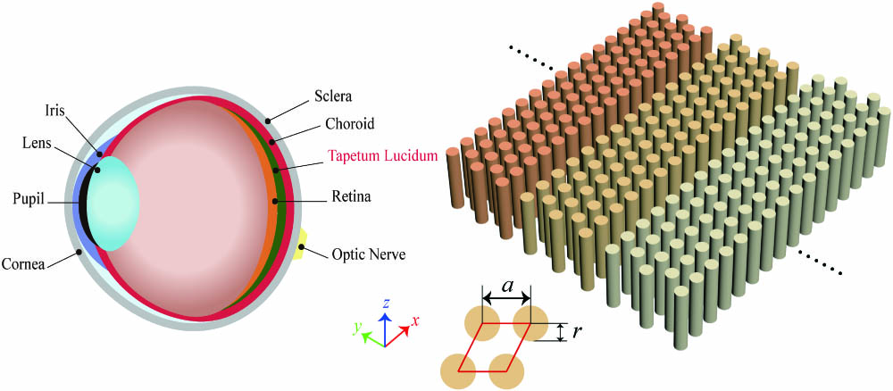
Firstly, let us consider the structure of a cat’s eye in detail. The left part of Fig. 1 demonstrates the structure of a cat’s eye, and the right one shows the schematic details of tapetum lucidum. As a reflective layer, tapetum lucidum is situated external to the retina, which can reflect light back onto the photoreceptors in the retina. Histologically, the cat’s tapetum lucidum consists of 10–12 layers of cells in its center, and each cell consists of 15–20 layers of rods, progressively thinning and eventually disappearing towards the periphery[
![]()
Figure 1.Structures of a cat’s eye (left picture) and tapetum lucidum (right picture). The tapetum lucidum lies behind the retina constituted by some columnar photonic crystals arranged in regular hexagons with different radii r and spaces a.
If we want to investigate the light propagation in photonic crystals, what we have to do is to calculate the corresponding photonic band structures. Hence, in order to be closer to reality, we choose different spaces of rods of 0.15 µm, 0.20 µm, and 0.25 µm to calculate the band structure, with their radius as 0.05 µm. Except for rods, the refractive index of the remaining parts of tapetum lucidum is about one, so we put some triangular array medium columns (refractive index
Photonic crystals possess different complete photonic bandgaps, as described by different colors in Fig. 2. The bandgaps for the case of
![]()
Figure 2.Photonic band structures for transverse electric (TE) modes of a triangular array of medium columns (refractive index n = 1.8, r = 0.05 µm) in the air. The inset at the corner shows the high symmetry points of the irreducible Brillouin zone (shaded light blue one). Note that complete photonic bandgaps happen for different colors with a = 0.15 µm, a = 0.20 µm, and a = 0.25 µm.
Now, we perform the simulations using the finite element software COMSOL Multiphysics. In simulations, we suppose the waves are in transverse electric (TE) polarization (the electric fields are along the
![]()
Figure 3.Electric field intensity |E|2 distributions of a Gaussian beam impinging on the Luneburg lens and the corresponding intensity comparison chart. (a)–(c) The electric field intensity of a Gaussian beam impinging on the Luneburg lens along y = 2 µm with different wavelengths. (d)–(f) The electric field intensity of a Gaussian beam impinging along the x axis, and the red line is along x = 3.5 µm. The detailed field distributions are inserted at the bottom of each figure, which are marked by the black dashed frames. (g)–(i) Intensity comparison with (red curves) and without (black curves) photonic crystals along the red line of (d)–(f).
Considering simulation limitations, we arranged three layers of photonic crystals behind the Luneburg lens. Although the number of layers we simulated is limited, it can still explain why there is a luminous look in cats’ eyes at night in some degree. In addition, riboflavin as the main component can absorb light in short wavelengths such as blue light and emits fluorescence in the wavelengths of green light. That is why we often see cats’ eyes appear turquoise.
If we impinge Gaussian beams with three different wavelengths along the
Our simulations, to some extent, illustrate why cats can distinguish things clearly even in a poor light environment. In other words, the intensity of the Luneburg lens without photonic crystals represents the intensity of the poor light environment. Even through the Luneburg lens (cats’ eyes) in a poor light environment, the intensity can be improved with the photonic crystals (tapetum lucidum).
Based on the simulation results we obtained above, we attempt to realize this in other wavelengths and compare the electric field intensities. As shown in Figs. 3(g)–3(i), we obtain the intensity statistics of comparison with and without photonic crystals along
![]()
Figure 4.Intensity comparison from 333 nm to 517 nm at the point (3.5, 0) and the reflectance of photonic crystals. (a) The solid blue and orange lines denote the intensity with and without photonic crystals, respectively. The dashed orange line denotes the intensity with PEC. (b) The solid blue and orange lines denote the reflectance of one layer and two layers of photonic crystals, respectively.
Therefore, the light focusing intensity of the lenses is greatly improved in a broad band of frequencies inspired by cats’ eyes. This reaffirms our idea that cats allow for the detection of light that is imperceptible to the human eyes because of the hundreds of layers of photonic crystals in tapetum lucidum.
There is a possibility the solid orange line would be above the blue line when the wavelength is large enough. As we can see from the blue line in the Fig. 4(a), the farther the layer from the Luneburg lens is, the worse the effect will be. As the wavelength increases, the layer is farther and farther away from the Luneburg lens, so it has the potential to be absolute that the solid orange line would be above the blue line. In this Letter, we only consider the case of three layers, and the solid orange line is always below the blue line.
Except for TE polarization, we also attempted the transverse magnetic (TM) polarization (the magnetic fields are along the
Only the wave both impinging and blocked by photonic crystals focusing at the point (3.5,0) can get the purpose of intensity enhancement. For the structure of Fig. 3, if we change the incident angles, the focusing intensity will decrease. Hence, we do some improvements based on the structure in Fig. 3, and the intensity can be increased even if the incident angle is changed. As shown in Figs. 5(d)–5(f), the retroreflector is composed of two elements: a Luneburg lens and three arcual structures with the same radii and spaces as in Fig. 3. Along the red line, we can plot comparison chart in Figs. 5(g)–5(i), where the focusing curve becomes sharper, and the intensity is enhanced for the different incident angles (the incident angle is defined as the deviation angle from the geometric symmetric axis of the structure, with the up deviation angle as “+”). From the simulation results, we can observe obviously that the improvement is effective and increases the stability of the effect compared to the structure in Fig. 3. Here, we choose 25 deg as an example in Fig. 5. If we use the plane wave as the source, the results of intensity enhancement also can be achieved, as shown by Figs. 5(a)–5(c).
![]()
Figure 5.Electric field intensity |E|2 distributions of a plane wave and a Gaussian beam impinging on the Luneburg lens and the corresponding intensity comparison chart. (a)–(c) The electric field intensities of the plane wave impinging on the Luneburg lens. (d)–(f) The electric field intensities of a Gaussian beam impinging on the Luneburg lens at 25° with different wavelengths. (g)–(i) Intensity comparison with (red curves) and without (black curves) photonic crystals along the red lines of (d)–(f).
3. Conclusion
Our bionic research not only allows people to better understand why cats can accurately capture prey even in a poor light environment and cats’ eyes often flash at night from the perspective of photonic crystals, but also confirm that the first layer of photonic crystals of cats’ eyes plays a deciding role in intensity enhancement. Based on the structure of tapetum lucidum, we integrate similar photonic structures to the Luneburg lens, and the focusing intensity is greatly improved in a broad band of frequencies. Furthermore, the effect of the retroreflector can also be demonstrated via this design. Thus, the integration of photonic crystals into the Luneburg lens shows the practicability and availability, which is a magical collision of photonic crystals and transformation optics. The amazing animal world has taught us a lot, and there are many more interesting optics phenomena that deserve to be explored in future.
References
[1] S. A. Davis, S. L. Burkett, N. H. Mendelson, S. Mann. Bacterial templating of ordered macrostructures in silica and silica-surfactant mesophases. Nature, 385, 420(1997).
[2] G. Cook, P. L. Timms, C. Göltner-Spickermann. Exact replication of biological structures by chemical vapor deposition of silica. Angew. Chem. Int. Edn., 42, 557(2003).
[3] R. Seshadri, F. C. Meldrum. Bioskeletons as templates for ordered, macroporous structures. Adv. Mater., 12, 1149(2000).
[4] S. Chia, J. Urano, F. Tamanoi, B. Dunn, J. I. Zink. Patterned hexagonal arrays of living cells in sol−gel silica films. J. Am. Chem. Soc., 122, 6488(2000).
[5] D. Yang, L. Qi, J. Ma. Eggshell membrane templating of hierarchically ordered macroporous networks composed of TiO2 tubes. Adv. Mater., 14, 1543(2002).
[6] A. Dong, Y. Wang, Y. Tang, N. Ren, Y. H. Zhang, Y. H. Yue, Z. Gao. Zeolitic tissue through wood cell templating. Adv. Mater., 14, 926(2002).
[7] A. R. Parker. Natural photonics for industrial inspiration. Philos. Trans. Royal Soc. A: Math. Phys. Eng. Sci., 367, 1759(2009).
[8] S. Tadepalli, J. M. Slocik, M. K. Gupta, R. R. Naik, S. Singamaneni. Bio-optics and bio-inspired optical materials. Chem. Rev., 117, 12705(2017).
[9] P. Vukusic, J. R. Sambles, C. R. Lawrence. Colour mixing in wing scales of a butterfly. Nature, 404, 457(2000).
[10] L. P. Biró, Z. Bálint, K. Kertész, Z. Vértesy, G. I. Márk, Z. E. Horváth, J. Balázs, D. Méhn, I. Kiricsi, V. Lousse, J.-P. Vigneron. Role of photonic-crystal-type structures in the thermal regulation of a Lycaenid butterfly sister species pair. Phys. Rev. E, 67, 021907(2003).
[11] J. Huang, X. Wang, Z. L. Wang. Controlled replication of butterfly wings for achieving tunable photonic properties. Nano Lett., 6, 2325(2006).
[12] A. R. Parker, V. L. Welch, D. Driver, N. Martini. Opal analogue discovered in a weevil. Nature, 426, 786(2003).
[13] M. F. Land, D.-E. Nilsson. Animal Eyes(2012).
[14] M. F. Land. The physics and biology of animal reflectors. Prog. Biophys. Mol. Boil., 24, 75(1972).
[15] M. H. Bernstein, D. C. Pease. Electron microscopy of the tapetum lucidum of the cat. J. Biophys. Biochem. Cytol., 5, 35(1959).
[16] J. A. Coles. Some reflective properties of the tapetum lucidum of the cat’s eye. J. Physiol., 212, 393(1971).
[17] F. J. Ollivier, D. A. Samuelson, D. E. Brooks, P. A. Lewis, M. E. Kallberg, A. M. Komáromy. Comparative morphology of the tapetum lucidum (among selected species). Vet. Ophthalmol., 7, 11(2004).
[18] F. G. Omenetto. Photonics in nature—opportunities and challenges at the biological interface. APL Photon., 4, 070402(2019).
[19] S. John. Strong localization of photons in certain disordered dielectric superlattices. Phys. Rev. Lett., 58, 2486(1987).
[20] E. Yablonovitch. Inhibited spontaneous emission in solid-state physics and electronics. Phys. Rev. Lett., 58, 2059(1987).
[21] R. D. Meade, J. N. Winn, J. D. Joannopoulos. Photonic Crystals: Molding the Flow of Light(1995).
[22] J. Sheng, J. Xie, J. Liu. Multiple super-resolution imaging in the second band of gradient lattice spacing photonic crystal flat lens. Chin. Opt. Lett., 18, 120501(2020).
[23] A. Arbabi, E. Arbabi, Y. Horie, S. M. Kamali, A. Faraon. Planar metasurface retroreflector. Nat. Photon., 11, 415(2017).
[24] T. Takatsuji, M. Goto, S. Osawa, R. Yin, T. Kurosawa. Whole-viewing-angle cat’s-eye retroreflector as a target of laser trackers. Meas. Sci. Technol., 10, N87(1999).
[25] Y. Fu, J. Li, Y. Xie, C. Shen, Y. Xu, H. Chen, S. A. Cummer. Compact acoustic retroreflector based on a mirrored Luneburg lens. Phys. Rev. Mater., 2, 105202(2018).
[26] U. Leonhardt, T. Philbin. Geometry and Light: The Science of Invisibility(2010).
[27] T. Tyc, L. Herzanova, M. Sarbort, K. Bering. Absolute instruments and perfect imaging in geometrical optics. New J. Phys., 13, 115004(2011).
[28] L. Xu, H. Chen. Conformal transformation optics. Nat. Photon., 9, 15(2015).
[29] J. B. Pendry. Negative refraction makes a perfect lens. Phys. Rev. Lett., 85, 3966(2000).
[30] H. Chen, W. Xiao. Morse lens. Chin. Opt. Lett., 18, 062403(2020).
[31] R. K. Luneburg. Mathematical Theory of Optics(1966).
[32] J. Eaton. On spherically symmetric lenses. Trans. IRE Prof. Group Antennas Propag., PGAP-4, 66(1952).
[33] R. W. Rodieck. The vertebrate retina: principles of structure and function. Arch. Ophthalmol., 58, 948(1974).


Set citation alerts for the article
Please enter your email address

© Copyright 2018-2021 | Chinese Laser Press. All Rights Reserved 沪ICP备15018463号-20